Information injection-pump assembly
ZEXEL
101603-4851
1016034851
ISUZU
1156023721
1156023721

Rating:
Service parts 101603-4851 INJECTION-PUMP ASSEMBLY:
1.
_
7.
COUPLING PLATE
8.
_
9.
_
11.
Nozzle and Holder
1-15300-214-1
12.
Open Pre:MPa(Kqf/cm2)
18.1{185}

15.
NOZZLE SET
Include in #1:
101603-4851
as INJECTION-PUMP ASSEMBLY
Include in #2:
104741-5510
as _
Cross reference number
ZEXEL
101603-4851
1016034851
ISUZU
1156023721
1156023721
Zexel num
Bosch num
Firm num
Name
Calibration Data:
Adjustment conditions
Test oil
1404 Test oil ISO4113 or {SAEJ967d}
1404 Test oil ISO4113 or {SAEJ967d}
Test oil temperature
degC
40
40
45
Nozzle and nozzle holder
105780-8140
Bosch type code
EF8511/9A
Nozzle
105780-0000
Bosch type code
DN12SD12T
Nozzle holder
105780-2080
Bosch type code
EF8511/9
Opening pressure
MPa
17.2
Opening pressure
kgf/cm2
175
Injection pipe
Outer diameter - inner diameter - length (mm) mm 6-2-600
Outer diameter - inner diameter - length (mm) mm 6-2-600
Overflow valve opening pressure
kPa
157
123
191
Overflow valve opening pressure
kgf/cm2
1.6
1.25
1.95
Tester oil delivery pressure
kPa
157
157
157
Tester oil delivery pressure
kgf/cm2
1.6
1.6
1.6
Direction of rotation (viewed from drive side)
Right R
Right R
Injection timing adjustment
Direction of rotation (viewed from drive side)
Right R
Right R
Injection order
1-5-3-6-
2-4
Pre-stroke
mm
3.6
3.55
3.65
Beginning of injection position
Drive side NO.1
Drive side NO.1
Difference between angles 1
Cal 1-5 deg. 60 59.5 60.5
Cal 1-5 deg. 60 59.5 60.5
Difference between angles 2
Cal 1-3 deg. 120 119.5 120.5
Cal 1-3 deg. 120 119.5 120.5
Difference between angles 3
Cal 1-6 deg. 180 179.5 180.5
Cal 1-6 deg. 180 179.5 180.5
Difference between angles 4
Cyl.1-2 deg. 240 239.5 240.5
Cyl.1-2 deg. 240 239.5 240.5
Difference between angles 5
Cal 1-4 deg. 300 299.5 300.5
Cal 1-4 deg. 300 299.5 300.5
Injection quantity adjustment
Adjusting point
-
Rack position
14.2
Pump speed
r/min
850
850
850
Average injection quantity
mm3/st.
101.4
99.8
103
Max. variation between cylinders
%
0
-2.5
2.5
Basic
*
Fixing the rack
*
Standard for adjustment of the maximum variation between cylinders
*
Injection quantity adjustment_02
Adjusting point
H
Rack position
9.5+-0.5
Pump speed
r/min
275
275
275
Average injection quantity
mm3/st.
8
6.7
9.3
Max. variation between cylinders
%
0
-14
14
Fixing the rack
*
Standard for adjustment of the maximum variation between cylinders
*
Injection quantity adjustment_03
Adjusting point
A
Rack position
R1(14.2)
Pump speed
r/min
850
850
850
Average injection quantity
mm3/st.
101.4
100.4
102.4
Basic
*
Fixing the lever
*
Boost pressure
kPa
20
20
Boost pressure
mmHg
150
150
Injection quantity adjustment_04
Adjusting point
B
Rack position
R1-0.7
Pump speed
r/min
1400
1400
1400
Average injection quantity
mm3/st.
92.8
89.6
96
Fixing the lever
*
Boost pressure
kPa
20
20
Boost pressure
mmHg
150
150
Injection quantity adjustment_05
Adjusting point
C
Rack position
R2(R1-0.
3)
Pump speed
r/min
550
550
550
Average injection quantity
mm3/st.
88.6
85.4
91.8
Fixing the lever
*
Boost pressure
kPa
20
20
Boost pressure
mmHg
150
150
Injection quantity adjustment_06
Adjusting point
I
Rack position
-
Pump speed
r/min
150
150
150
Average injection quantity
mm3/st.
90
90
98
Fixing the lever
*
Rack limit
*
Boost compensator adjustment
Pump speed
r/min
550
550
550
Rack position
R2-1.6
Boost pressure
kPa
2
2
4.7
Boost pressure
mmHg
15
15
35
Boost compensator adjustment_02
Pump speed
r/min
550
550
550
Rack position
R2-0.95
Boost pressure
kPa
4.7
4.7
7.4
Boost pressure
mmHg
35
35
55
Boost compensator adjustment_03
Pump speed
r/min
550
550
550
Rack position
R2(R1-0.
3)
Boost pressure
kPa
13.3
13.3
13.3
Boost pressure
mmHg
100
100
100
Timer adjustment
Pump speed
r/min
1325--
Advance angle
deg.
0
0
0
Remarks
Start
Start
Timer adjustment_02
Pump speed
r/min
1275
Advance angle
deg.
0.5
Timer adjustment_03
Pump speed
r/min
1400
Advance angle
deg.
1
0.5
1.5
Remarks
Finish
Finish
Test data Ex:
Governor adjustment
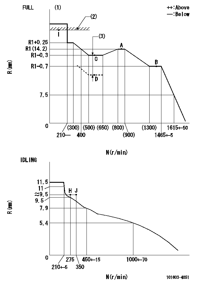
N:Pump speed
R:Rack position (mm)
(1)Torque cam stamping: T1
(2)RACK LIMIT
(3)Boost compensator stroke: BCL
----------
T1=C94 BCL=1.6+-0.1mm
----------
----------
T1=C94 BCL=1.6+-0.1mm
----------
Speed control lever angle

F:Full speed
I:Idle
(1)Use the hole at R = aa
(2)Stopper bolt set position 'H'
----------
aa=35mm
----------
a=43deg+-5deg b=42deg+-3deg
----------
aa=35mm
----------
a=43deg+-5deg b=42deg+-3deg
Stop lever angle

N:Pump normal
S:Stop the pump.
----------
----------
a=25deg+-5deg b=40deg+-5deg
----------
----------
a=25deg+-5deg b=40deg+-5deg
Timing setting

(1)Pump vertical direction
(2)Position of timer's threaded hole at No 1 cylinder's beginning of injection
(3)B.T.D.C.: aa
(4)-
----------
aa=13deg
----------
a=(60deg)
----------
aa=13deg
----------
a=(60deg)
Information:
Illustration 1 g00564355
7W-2743 Electronic Speed Switch (ESS)
(1) Push button for Overspeed Verification
(2) Reset button
(3) Overspeed indicator lamp
(4) Seal screw plug for adjusting the engine overspeed
(5) Seal screw plug for adjusting the crank terminate speed
(6) Seal screw plug for adjusting the oil step pressure speed setting The procedure for the magnetic pickup test will determine if the operation of the magnetic pickup is correct.
Connect a 6V-7070 Digital Multimeter to the "COM" terminal and the "SIG" terminal. The terminals are (ESS-3)and (ESS-4) of the ESS. Set the meter voltage scale to a scale that is greater than 1.5 VAC. Start the engine. Run the engine at low idle or 600 rpm. Choose the one that is larger. If the voltage that is measured is 1.5 VAC or more, the operation of the magnetic pickup is correct. If the voltage is less than 1.5 VAC, go to Step 2.
Stop the engine. Disconnect the wiring for the magnetic pickup at the plug-in connector. Connect the voltmeter to the connector terminals of the magnetic pickup. Start the engine. Run the engine at low idle or 600 rpm. Choose the one that is larger. If the voltage that is measured is 1.5 VAC or more, repair the wiring that is between the magnetic pickup and the ESS. If the voltage is less than 1.5 VAC, go to Step 3.
Illustration 2 g00564913
Magnetic pickup
(1) Clearance
(2) Magnetic pickup
(3) Wires to the connector
(4) Locknut
(5) Flywheel housing
(6) Ring gear
Loosen locknut (4) and turn magnetic pickup (2) in the counterclockwise direction in order to remove magnetic pickup (2) from flywheel housing (5). Turn the flywheel until a gear tooth of ring gear (6) is directly in the center of the threaded hole for magnetic pickup (2). Install magnetic pickup (2) in flywheel housing (5).
Turn magnetic pickup (2) in the clockwise direction until the end of magnetic pickup (2) slightly touches the gear tooth. Turn the magnetic pickup for one-half turn in the counterclockwise direction in order to set correct clearance (1). Tighten locknut (4) to a torque of 45 7 N m (33 5 lb ft). Note: Do not allow the magnetic pickup to turn while the locknut is tightened.
Repeat Step 2. If the voltage is still less than 1.5 VAC, replace the magnetic pickup.