Information injection-pump assembly
ZEXEL
101603-4820
1016034820
ISUZU
1156023710
1156023710

Rating:
Cross reference number
ZEXEL
101603-4820
1016034820
ISUZU
1156023710
1156023710
Zexel num
Bosch num
Firm num
Name
Calibration Data:
Adjustment conditions
Test oil
1404 Test oil ISO4113 or {SAEJ967d}
1404 Test oil ISO4113 or {SAEJ967d}
Test oil temperature
degC
40
40
45
Nozzle and nozzle holder
105780-8140
Bosch type code
EF8511/9A
Nozzle
105780-0000
Bosch type code
DN12SD12T
Nozzle holder
105780-2080
Bosch type code
EF8511/9
Opening pressure
MPa
17.2
Opening pressure
kgf/cm2
175
Injection pipe
Outer diameter - inner diameter - length (mm) mm 6-2-600
Outer diameter - inner diameter - length (mm) mm 6-2-600
Overflow valve opening pressure
kPa
157
123
191
Overflow valve opening pressure
kgf/cm2
1.6
1.25
1.95
Tester oil delivery pressure
kPa
157
157
157
Tester oil delivery pressure
kgf/cm2
1.6
1.6
1.6
Direction of rotation (viewed from drive side)
Left L
Left L
Injection timing adjustment
Direction of rotation (viewed from drive side)
Left L
Left L
Injection order
1-5-3-6-
2-4
Pre-stroke
mm
3.7
3.65
3.75
Beginning of injection position
Governor side NO.1
Governor side NO.1
Difference between angles 1
Cal 1-5 deg. 60 59.5 60.5
Cal 1-5 deg. 60 59.5 60.5
Difference between angles 2
Cal 1-3 deg. 120 119.5 120.5
Cal 1-3 deg. 120 119.5 120.5
Difference between angles 3
Cal 1-6 deg. 180 179.5 180.5
Cal 1-6 deg. 180 179.5 180.5
Difference between angles 4
Cyl.1-2 deg. 240 239.5 240.5
Cyl.1-2 deg. 240 239.5 240.5
Difference between angles 5
Cal 1-4 deg. 300 299.5 300.5
Cal 1-4 deg. 300 299.5 300.5
Injection quantity adjustment
Adjusting point
-
Rack position
11.6
Pump speed
r/min
700
700
700
Average injection quantity
mm3/st.
80.2
78.6
81.8
Max. variation between cylinders
%
0
-2.5
2.5
Basic
*
Fixing the rack
*
Standard for adjustment of the maximum variation between cylinders
*
Injection quantity adjustment_02
Adjusting point
H
Rack position
9.5+-0.5
Pump speed
r/min
260
260
260
Average injection quantity
mm3/st.
10.7
8.7
12.7
Max. variation between cylinders
%
0
-14
14
Fixing the rack
*
Standard for adjustment of the maximum variation between cylinders
*
Injection quantity adjustment_03
Adjusting point
A
Rack position
R1(11.6)
Pump speed
r/min
700
700
700
Average injection quantity
mm3/st.
80.2
79.2
81.2
Basic
*
Fixing the lever
*
Injection quantity adjustment_04
Adjusting point
B
Rack position
R1+0.25
Pump speed
r/min
1350
1350
1350
Average injection quantity
mm3/st.
96.4
93.2
99.6
Fixing the lever
*
Injection quantity adjustment_05
Adjusting point
C
Rack position
R1(11.6)
Pump speed
r/min
550
550
550
Average injection quantity
mm3/st.
75
71.8
78.2
Fixing the lever
*
Injection quantity adjustment_06
Adjusting point
I
Rack position
14.1+-0.
5
Pump speed
r/min
100
100
100
Average injection quantity
mm3/st.
96.5
96.5
106.5
Fixing the lever
*
Rack limit
*
Timer adjustment
Pump speed
r/min
1150--
Advance angle
deg.
0
0
0
Remarks
Start
Start
Timer adjustment_02
Pump speed
r/min
1100
Advance angle
deg.
0.5
Timer adjustment_03
Pump speed
r/min
1250
Advance angle
deg.
3.1
2.6
3.6
Timer adjustment_04
Pump speed
r/min
1350
Advance angle
deg.
6
5.5
6.5
Remarks
Finish
Finish
Test data Ex:
Governor adjustment
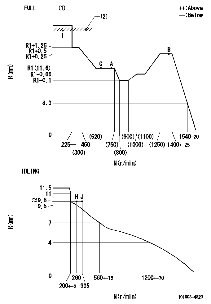
N:Pump speed
R:Rack position (mm)
(1)Torque cam stamping: T1
(2)RACK LIMIT
----------
T1=C53
----------
----------
T1=C53
----------
Speed control lever angle

F:Full speed
I:Idle
(1)Use the pin at R = aa
(2)Stopper bolt set position 'H'
----------
aa=67.5mm
----------
a=18deg+-5deg b=34deg+-3deg
----------
aa=67.5mm
----------
a=18deg+-5deg b=34deg+-3deg
Stop lever angle
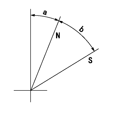
N:Pump normal
S:Stop the pump.
----------
----------
a=25deg+-5deg b=40deg+-5deg
----------
----------
a=25deg+-5deg b=40deg+-5deg
Timing setting

(1)Pump vertical direction
(2)Position of timer's threaded hole at No 1 cylinder's beginning of injection
(3)B.T.D.C.: aa
(4)-
----------
aa=14deg
----------
a=(40deg)
----------
aa=14deg
----------
a=(40deg)
Information:
Specifications
Illustration 42 g03135400
Table 13
Fuel Injection Pump Camshaft
Model Dimension A Dimension B Dimension C Dimension D Dimension E
3064
3066 40.72 0.25 mm (1.603 0.010 inch) 20.003 0.005 mm (0.7875 0.0002 inch) 11.13 0.25 mm (0.438 0.010 inch) 16.955 0.005 mm (0.6675 0.0002 inch) 16.26 0.25 mm (0.640 0.010 inch) Note: All sprayed edges should be rounded with a 0.795 mm (0.0313 inch) radius.Storage Procedures
Proper protection of the components from corrosion is important. Corrosion will start in as little as one hour after the components have been cleaned.When the components will not be inspected for one hour or less the components should be coated with a rust or corrosion inhibitor or coated with clean engine oil. The components should be individually wrapped to prevent contamination, and should be stored in a protected area to avoid damage. See Illustration 43.When the components will not be inspected in two days or more the components should be coated with a rust or corrosion inhibitor or coated with clean engine oil and should be placed in a container which is clean and structurally solid. The container should be covered or wrapped in plastic to prevent damage and contamination to the components. See Illustration 44.Refer to SEHS9031Special Instruction, "Storage Procedure for Caterpillar Products" for more information.
Illustration 43 g06278538
Example of protection for a component that is stored for a shorter term
Illustration 44 g06278539
Example of protection for a component that is stored for a longer period