Information injection-pump assembly
ZEXEL
101603-4812
1016034812
ISUZU
1156022153
1156022153

Rating:
Cross reference number
ZEXEL
101603-4812
1016034812
ISUZU
1156022153
1156022153
Zexel num
Bosch num
Firm num
Name
Calibration Data:
Adjustment conditions
Test oil
1404 Test oil ISO4113 or {SAEJ967d}
1404 Test oil ISO4113 or {SAEJ967d}
Test oil temperature
degC
40
40
45
Nozzle and nozzle holder
105780-8140
Bosch type code
EF8511/9A
Nozzle
105780-0000
Bosch type code
DN12SD12T
Nozzle holder
105780-2080
Bosch type code
EF8511/9
Opening pressure
MPa
17.2
Opening pressure
kgf/cm2
175
Injection pipe
Outer diameter - inner diameter - length (mm) mm 6-2-600
Outer diameter - inner diameter - length (mm) mm 6-2-600
Overflow valve opening pressure
kPa
157
123
191
Overflow valve opening pressure
kgf/cm2
1.6
1.25
1.95
Tester oil delivery pressure
kPa
157
157
157
Tester oil delivery pressure
kgf/cm2
1.6
1.6
1.6
Direction of rotation (viewed from drive side)
Right R
Right R
Injection timing adjustment
Direction of rotation (viewed from drive side)
Right R
Right R
Injection order
1-5-3-6-
2-4
Pre-stroke
mm
3.6
3.55
3.65
Beginning of injection position
Drive side NO.1
Drive side NO.1
Difference between angles 1
Cal 1-5 deg. 60 59.5 60.5
Cal 1-5 deg. 60 59.5 60.5
Difference between angles 2
Cal 1-3 deg. 120 119.5 120.5
Cal 1-3 deg. 120 119.5 120.5
Difference between angles 3
Cal 1-6 deg. 180 179.5 180.5
Cal 1-6 deg. 180 179.5 180.5
Difference between angles 4
Cyl.1-2 deg. 240 239.5 240.5
Cyl.1-2 deg. 240 239.5 240.5
Difference between angles 5
Cal 1-4 deg. 300 299.5 300.5
Cal 1-4 deg. 300 299.5 300.5
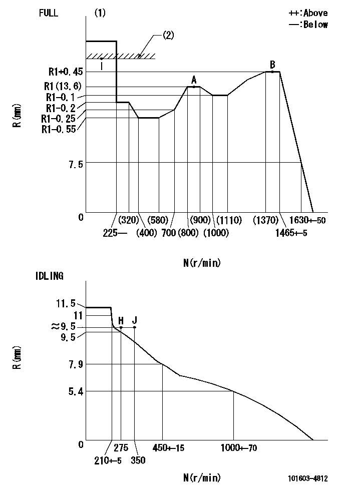
Injection quantity adjustment
Adjusting point
-
Rack position
13.6
Pump speed
r/min
850
850
850
Average injection quantity
mm3/st.
87
85.4
88.6
Max. variation between cylinders
%
0
-2.5
2.5
Basic
*
Fixing the rack
*
Standard for adjustment of the maximum variation between cylinders
*
Injection quantity adjustment_02
Adjusting point
H
Rack position
9.5+-0.5
Pump speed
r/min
275
275
275
Average injection quantity
mm3/st.
8
6.7
9.3
Max. variation between cylinders
%
0
-14
14
Fixing the rack
*
Standard for adjustment of the maximum variation between cylinders
*
Injection quantity adjustment_03
Adjusting point
A
Rack position
R1(13.6)
Pump speed
r/min
850
850
850
Average injection quantity
mm3/st.
87
86
88
Basic
*
Fixing the lever
*
Injection quantity adjustment_04
Adjusting point
B
Rack position
R1+0.45
Pump speed
r/min
1400
1400
1400
Average injection quantity
mm3/st.
102.4
99.2
105.6
Fixing the lever
*
Injection quantity adjustment_05
Adjusting point
I
Rack position
-
Pump speed
r/min
150
150
150
Average injection quantity
mm3/st.
95
95
103
Fixing the lever
*
Rack limit
*
Timer adjustment
Pump speed
r/min
1325--
Advance angle
deg.
0
0
0
Remarks
Start
Start
Timer adjustment_02
Pump speed
r/min
1275
Advance angle
deg.
0.5
Timer adjustment_03
Pump speed
r/min
1400
Advance angle
deg.
0.5
0
1
Remarks
Finish
Finish
Test data Ex:
Governor adjustment
N:Pump speed
R:Rack position (mm)
(1)Torque cam stamping: T1
(2)RACK LIMIT
----------
T1=C96
----------
----------
T1=C96
----------
Speed control lever angle

F:Full speed
I:Idle
(1)Use the hole at R = aa
(2)Stopper bolt setting
----------
aa=35mm
----------
a=43deg+-5deg b=40deg+-3deg
----------
aa=35mm
----------
a=43deg+-5deg b=40deg+-3deg
Stop lever angle
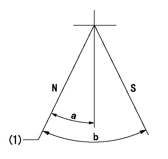
N:Pump normal
S:Stop the pump.
(1)Stopper bolt setting
----------
----------
a=25deg+-5deg b=40deg+-5deg
----------
----------
a=25deg+-5deg b=40deg+-5deg
0000001501 ACS

(A) Set screw
(B) Push rod 1
(C) Push rod 2
(D) Cover
1. Aneroid compensator unit adjustment
(1)Select the push rod 2 to obtain L2.
(2)Screw in (A) to obtain L1.
2. Adjustment when mounting the governor.
(1)Set the speed of the pump to N1 r/min and fix the control lever at the full set position.
(2)Screw in the aneroid compensator to obtain the performance shown in the graph above.
(3)As there is hysterisis, measure when the absolute pressure drops.
(4)Hysterisis must not exceed rack position = h1.
----------
N1=1400r/min L1=(1.5)mm L2=11+-0.5mm h1=0.15mm
----------
Ra=R2(R1+0.45)mm Rb=R2-0.45mm Pa=92.6+-2.7kPa(695+-20mmHg) Pb=70.1+-0.7kPa(526+-5mmHg) Q1=(102.4)+-1.6cm3/1000st Q2=(94.3)+-1.6cm3/1000st
----------
N1=1400r/min L1=(1.5)mm L2=11+-0.5mm h1=0.15mm
----------
Ra=R2(R1+0.45)mm Rb=R2-0.45mm Pa=92.6+-2.7kPa(695+-20mmHg) Pb=70.1+-0.7kPa(526+-5mmHg) Q1=(102.4)+-1.6cm3/1000st Q2=(94.3)+-1.6cm3/1000st
Timing setting

(1)Pump vertical direction
(2)Position of timer's threaded hole at No 1 cylinder's beginning of injection
(3)B.T.D.C.: aa
(4)-
----------
aa=14deg
----------
a=(60deg)
----------
aa=14deg
----------
a=(60deg)
Information:
Close the gauge protector valve ( 0 to 40,000 kPa (0 to 5,800 psi) gauge).
Visually inspect the pattern of the fuel nozzle for a uniform spray.Note: For this test, each full stroke of the pump should be performed in less than one second.
Rapidly increase the pressure on the fuel nozzle until fluid sprays from the tip of the fuel nozzle.
Test fluid should spray from the tip of the nozzle in a pattern that is uniform. Refer to Illustration 2.
Check the individual spray orifices for partial plugging.
Use a moderate pump stroke to open the valve of the fuel nozzle.
During the pump stroke, view the individual spray orifices for partial plugging.The test fluid should spray uniformly from all the orifices.If an orifice is plugged or the pattern is distorted, clean the fuel nozzle orifices and repeat this test. Refer to Special Instruction, SEHS8627, "Use of 8S-2245 Nozzle Cleaning Tool Group" for instructions on tool usage and cleaning procedures.Test the Fuel Nozzle for Seal Leakage
Note: Testing for seal leakage is not a requirement for the 104-9450 Fuel Nozzle, 104-9452 Fuel Nozzle, 104-9453 Fuel Nozzle, or the 104-9454 Fuel Nozzle. Do not perform this test on these fuel nozzles.
Illustration 3 g00453789
Typical example of a 7000 Series fuel nozzle
Remove the cloth from the top of the nozzle.
Prior to performing this test, install a new seal washer on purging screw (A) and reinstall the purging screw into the fuel nozzle.
Illustration 4 g00453809
Tighten purging screw (D) or purging screw (E) to a torque of 2.2 0.8 N m (20 7 lb in). Note: Use a 6V-4980 Torque Screwdriver Tool Group to torque the purging screw.
Apply a test pressure of 13,800 kPa (2,000 psi) to the fuel nozzle.Note: Due to the large amount of test fluid that is delivered to the fuel nozzle, hydraulic lock may prevent the nozzle from opening during this test. If a hydraulic lock occurs, slowly loosen the adapter fitting to relieve the pressure on the fuel nozzle valve assembly.If there is leakage at the purging screw, install a new 8C-3234 Screw and a 114-3364 Washer as replacement parts. Retest the fuel nozzle for leaks.Do not use the nozzle if there is leakage that cannot be repaired at purging screw (A), upper seal joint (B), or lower seal joint (C).Returning Fuel Nozzles to Service
Illustration 5 g00453817Prior to returning fuel nozzles to service, install a new seal washer (3) and install a new carbon dam (4) on the fuel nozzle (1).Use 6V-4979 Carbon Seal Installation Tool (2) to install a new carbon dam (4).Table 5 contains part numbers for the replacement of the fuel nozzle seal washers.
Table 5
Seal Washers
Fuel Nozzle Washer (Color) Washer Thickness
8N-7004 4W-3914 (Gray) 1.27 mm (0.050 inch)
4W-7012
4W-7013
4W-7014
4W-7015 4W-6060 (Blue) 3.18 mm (0.125 inch)
4W-7018
4W-7019
4W-7020
4W-7021
4W-7022
7W-7045
100-7552
100-7562
100-7563
104-3377
167-7489
170-5181
170-5183 7W-4482 (Green) 3.18 mm (0.125 inch)
133-3896 7W-4483 (Red) 2.54 mm (0.100 inch)
4W-7011
4W-7016
7W-7024 7W-4485 (Copper) 1.27 mm (0.050 inch)
8N-7003
7W-7038
8N-7005
100-7559
100-7561
100-7564
104-9450
104-9452
104-9453
104-9454
131-3190
154-3198
170-5187 7W-4486 (Violet) 1.84 mm (0.072 inch)
4W-7017
7W-7026
7W-7030
7W-7031
7W-7032
7W-7033
7W-7035
7W-7037
7W-7040
7W-7041
7W-7042
7W-7043
7W-7044
8N-7007
100-7550
100-7551
100-7556
100-7557
100-7558
100-7560
100-7565
100-7567
100-7600
121-4353
127-9792
127-9793
129-1351
130-1804
130-1806
130-5187
130-5190
131-0811
131-0812
131-1242
131-1243
131-7937
134-0944
171-4093 7W-4487 (Black) 1.27 mm (0.050 inch)
7W-7023