Information injection-pump assembly
ZEXEL
101603-4802
1016034802
ISUZU
1156023282
1156023282

Rating:
Service parts 101603-4802 INJECTION-PUMP ASSEMBLY:
1.
_
7.
COUPLING PLATE
8.
_
9.
_
11.
Nozzle and Holder
1-15300-142-0
12.
Open Pre:MPa(Kqf/cm2)
18.1(185)
15.
NOZZLE SET
Include in #1:
101603-4802
as INJECTION-PUMP ASSEMBLY
Include in #2:
104741-1482
as _
Cross reference number
ZEXEL
101603-4802
1016034802
ISUZU
1156023282
1156023282
Zexel num
Bosch num
Firm num
Name
101603-4802
1156023282 ISUZU
INJECTION-PUMP ASSEMBLY
6BG1 * K
6BG1 * K
Calibration Data:
Adjustment conditions
Test oil
1404 Test oil ISO4113 or {SAEJ967d}
1404 Test oil ISO4113 or {SAEJ967d}
Test oil temperature
degC
40
40
45
Nozzle and nozzle holder
105780-8140
Bosch type code
EF8511/9A
Nozzle
105780-0000
Bosch type code
DN12SD12T
Nozzle holder
105780-2080
Bosch type code
EF8511/9
Opening pressure
MPa
17.2
Opening pressure
kgf/cm2
175
Injection pipe
Outer diameter - inner diameter - length (mm) mm 6-2-600
Outer diameter - inner diameter - length (mm) mm 6-2-600
Overflow valve
131424-4920
Overflow valve opening pressure
kPa
127
107
147
Overflow valve opening pressure
kgf/cm2
1.3
1.1
1.5
Tester oil delivery pressure
kPa
157
157
157
Tester oil delivery pressure
kgf/cm2
1.6
1.6
1.6
Direction of rotation (viewed from drive side)
Right R
Right R
Injection timing adjustment
Direction of rotation (viewed from drive side)
Right R
Right R
Injection order
1-5-3-6-
2-4
Pre-stroke
mm
3.6
3.55
3.65
Rack position
Point A R=A
Point A R=A
Beginning of injection position
Drive side NO.1
Drive side NO.1
Difference between angles 1
Cal 1-5 deg. 60 59.5 60.5
Cal 1-5 deg. 60 59.5 60.5
Difference between angles 2
Cal 1-3 deg. 120 119.5 120.5
Cal 1-3 deg. 120 119.5 120.5
Difference between angles 3
Cal 1-6 deg. 180 179.5 180.5
Cal 1-6 deg. 180 179.5 180.5
Difference between angles 4
Cyl.1-2 deg. 240 239.5 240.5
Cyl.1-2 deg. 240 239.5 240.5
Difference between angles 5
Cal 1-4 deg. 300 299.5 300.5
Cal 1-4 deg. 300 299.5 300.5
Injection quantity adjustment
Adjusting point
-
Rack position
10.8
Pump speed
r/min
900
900
900
Average injection quantity
mm3/st.
54.3
52.7
55.9
Max. variation between cylinders
%
0
-2.5
2.5
Basic
*
Fixing the rack
*
Standard for adjustment of the maximum variation between cylinders
*
Injection quantity adjustment_02
Adjusting point
H
Rack position
9.5+-0.5
Pump speed
r/min
290
290
290
Average injection quantity
mm3/st.
8
6.7
9.3
Max. variation between cylinders
%
0
-14
14
Fixing the rack
*
Standard for adjustment of the maximum variation between cylinders
*
Injection quantity adjustment_03
Adjusting point
A
Rack position
R1(10.8)
Pump speed
r/min
900
900
900
Average injection quantity
mm3/st.
54.3
53.3
55.3
Basic
*
Fixing the lever
*
Injection quantity adjustment_04
Adjusting point
B
Rack position
R1(10.8)
Pump speed
r/min
1500
1500
1500
Average injection quantity
mm3/st.
60
56.8
63.2
Fixing the lever
*
Timer adjustment
Pump speed
r/min
1310--
Advance angle
deg.
0
0
0
Remarks
Start
Start
Timer adjustment_02
Pump speed
r/min
1260
Advance angle
deg.
0.5
Timer adjustment_03
Pump speed
r/min
1500
Advance angle
deg.
4.5
4
5
Remarks
Finish
Finish
Test data Ex:
Governor adjustment
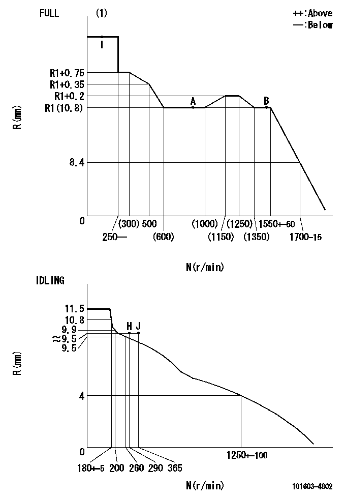
N:Pump speed
R:Rack position (mm)
(1)Torque cam stamping: T1
----------
T1=C78
----------
----------
T1=C78
----------
Speed control lever angle

F:Full speed
I:Idle
(1)Use the hole at R = aa
(2)Stopper bolt set position 'H'
----------
aa=35mm
----------
a=42deg+-5deg b=(33deg)+-3deg
----------
aa=35mm
----------
a=42deg+-5deg b=(33deg)+-3deg
Stop lever angle

N:Pump normal
S:Stop the pump.
(1)Stopper bolt setting
----------
----------
a=25deg+-5deg b=40deg+-5deg
----------
----------
a=25deg+-5deg b=40deg+-5deg
0000001501 ACS

(A) Set screw
(B) Push rod 1
(C) Push rod 2
(D) Cover
1. Aneroid compensator unit adjustment
(1)Select the push rod 2 to obtain L2.
(2)Screw in (A) to obtain L1.
2. Adjustment when mounting the governor.
(1)Set the speed of the pump to N1 r/min and fix the control lever at the full set position.
(2)Screw in the aneroid compensator to obtain the performance shown in the graph above.
(3)As there is hysterisis, measure when the absolute pressure drops.
(4)Hysterisis must not exceed rack position = h1.
----------
N1=900r/min L1=(1.5)mm L2=11+-0.5mm h1=0.15mm
----------
Ra=R1(10.8)mm Rb=R1-0.5mm Pa=84.5+-2.7kPa(634+-20mmHg) Pb=70.1+-0.7kPa(526+-5mmHg) Q1=54.3+-1cm3/1000st Q2=(40.4)+-1.6cm3/1000st
----------
N1=900r/min L1=(1.5)mm L2=11+-0.5mm h1=0.15mm
----------
Ra=R1(10.8)mm Rb=R1-0.5mm Pa=84.5+-2.7kPa(634+-20mmHg) Pb=70.1+-0.7kPa(526+-5mmHg) Q1=54.3+-1cm3/1000st Q2=(40.4)+-1.6cm3/1000st
Timing setting

(1)Pump vertical direction
(2)Position of timer's threaded hole at No 1 cylinder's beginning of injection
(3)B.T.D.C.: aa
(4)-
----------
aa=13deg
----------
a=(60deg)
----------
aa=13deg
----------
a=(60deg)
Information:
Illustration 39 g00367353
Set the drive speed to "Col 4". Place a straight edge across the opening in the shutdown rod and the shutdown rod nut (F). Use a 7/16 inch open end wrench in order to turn the shutdown rod nut (F) counterclockwise until the governor begins to shut down. Once the governor begins to shut down, turn the nut clockwise one full turn.Adjustment Of The Shutdown Device
Note: The electric shutdown device and the pressure shutdown device should be checked prior to the installation, after the installation, and at 1000 hour intervals thereafter.
Failure to test, inspect and maintain these items could result in faulty operation and possible severe engine damage if an emergency shutdown situation occurs.
The electric shutdown is either an Energize-To-Shutoff (ETS) or an Energize-To-Run (ETR). Identify the type of shutdown device in your governor, and make a note of the type of shutdown device.
Visually inspect the pressure shutdown components for signs of burrs, nicks, scoring and/or wear. Repair the components if evidence of a problem exists. Inspect the pressure shutdown gasket. Determine if the gasket is reusable. If necessary, replace the gasket.
Illustration 40 g00367319
(F) Shutdown Rod Nut. (J) Shutdown Rod. (II) Solenoid. (JJ) Jam Nut. (KK) Set Screw. (LL) Shutdown Plunger. (MM) Solenoid Plunger. (NN) Pivot Pin. (PP) Shutdown Lever.
Visually inspect the electric shutdown device and determine if there is any component wear. If the shutdown is an ETS version, pay particular attention to the connection of the shutdown solenoid's plunger and the shutdown lever's link pin.If there is evidence of wear, replace the solenoid. Inspect the gasket on the electric shutdown. Determine if the gasket is reusable. If necessary, replace the gasket.Check the size of spacer on the solenoid plunger in the electric shutdown. Refer to the Service Magazine Article November 19,, "Field Replacement of Spacer to Correct Possible Sticking in Woodward 3161 Governor Electric Shutoff Group".Adjustment Of The Electric Shutdown Solenoid
Energize-To-Shutoff (ETS)
Place the housing of the electric shutdown in a vise. Use copper jaws or shop towels in order to protect the sides of the aluminum die cast housing. Do NOT excessively tighten the vise.Loosen the jam nut (JJ) that holds the solenoid in the electric shutdown's housing. Remove the solenoid coil (II) in order to expose the shutdown plunger (MM) .Note: Loctite 222 is used on the threads of the solenoid coil during manufacturing. In addition, the jam nut is tightened to a torque of 75 N m (55.5 lb ft).
Carefully clean any dirt, metal filings or metal chips from the solenoid plunger and from the cavity in the solenoid coil. Turn the jam nut on the solenoid coil so that the nut will not interfere with the adjustment of the solenoid coil. Reinstall the solenoid coil in the electric shutdown's housing by turning the coil four times.
Hold the housing and the gasket on a
Have questions with 101603-4802?
Group cross 101603-4802 ZEXEL
Isuzu
101603-4802
1156023282
INJECTION-PUMP ASSEMBLY
6BG1
6BG1