Information injection-pump assembly
ZEXEL
101603-4801
1016034801
ISUZU
1156023281
1156023281

Rating:
Cross reference number
ZEXEL
101603-4801
1016034801
ISUZU
1156023281
1156023281
Zexel num
Bosch num
Firm num
Name
Calibration Data:
Adjustment conditions
Test oil
1404 Test oil ISO4113 or {SAEJ967d}
1404 Test oil ISO4113 or {SAEJ967d}
Test oil temperature
degC
40
40
45
Nozzle and nozzle holder
105780-8140
Bosch type code
EF8511/9A
Nozzle
105780-0000
Bosch type code
DN12SD12T
Nozzle holder
105780-2080
Bosch type code
EF8511/9
Opening pressure
MPa
17.2
Opening pressure
kgf/cm2
175
Injection pipe
Outer diameter - inner diameter - length (mm) mm 6-2-600
Outer diameter - inner diameter - length (mm) mm 6-2-600
Overflow valve
131424-4920
Overflow valve opening pressure
kPa
127
107
147
Overflow valve opening pressure
kgf/cm2
1.3
1.1
1.5
Tester oil delivery pressure
kPa
157
157
157
Tester oil delivery pressure
kgf/cm2
1.6
1.6
1.6
Direction of rotation (viewed from drive side)
Right R
Right R
Injection timing adjustment
Direction of rotation (viewed from drive side)
Right R
Right R
Injection order
1-5-3-6-
2-4
Pre-stroke
mm
3.6
3.55
3.65
Rack position
Point A R=A
Point A R=A
Beginning of injection position
Drive side NO.1
Drive side NO.1
Difference between angles 1
Cal 1-5 deg. 60 59.5 60.5
Cal 1-5 deg. 60 59.5 60.5
Difference between angles 2
Cal 1-3 deg. 120 119.5 120.5
Cal 1-3 deg. 120 119.5 120.5
Difference between angles 3
Cal 1-6 deg. 180 179.5 180.5
Cal 1-6 deg. 180 179.5 180.5
Difference between angles 4
Cyl.1-2 deg. 240 239.5 240.5
Cyl.1-2 deg. 240 239.5 240.5
Difference between angles 5
Cal 1-4 deg. 300 299.5 300.5
Cal 1-4 deg. 300 299.5 300.5
Injection quantity adjustment
Adjusting point
-
Rack position
10.9
Pump speed
r/min
900
900
900
Average injection quantity
mm3/st.
58
56.4
59.6
Max. variation between cylinders
%
0
-2.5
2.5
Basic
*
Fixing the rack
*
Standard for adjustment of the maximum variation between cylinders
*
Injection quantity adjustment_02
Adjusting point
H
Rack position
9.5+-0.5
Pump speed
r/min
290
290
290
Average injection quantity
mm3/st.
8
6.7
9.3
Max. variation between cylinders
%
0
-14
14
Fixing the rack
*
Standard for adjustment of the maximum variation between cylinders
*
Injection quantity adjustment_03
Adjusting point
A
Rack position
R1(10.9)
Pump speed
r/min
900
900
900
Average injection quantity
mm3/st.
58
57
59
Basic
*
Fixing the lever
*
Injection quantity adjustment_04
Adjusting point
B
Rack position
R1(10.9)
Pump speed
r/min
1500
1500
1500
Average injection quantity
mm3/st.
64.1
60.9
67.3
Fixing the lever
*
Timer adjustment
Pump speed
r/min
1310--
Advance angle
deg.
0
0
0
Remarks
Start
Start
Timer adjustment_02
Pump speed
r/min
1260
Advance angle
deg.
0.5
Timer adjustment_03
Pump speed
r/min
1500
Advance angle
deg.
4.5
4
5
Remarks
Finish
Finish
Test data Ex:
Governor adjustment
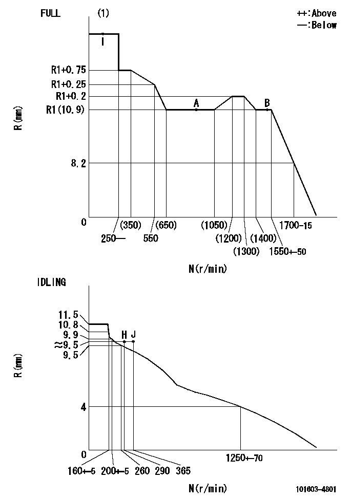
N:Pump speed
R:Rack position (mm)
(1)Torque cam stamping: T1
----------
T1=C78
----------
----------
T1=C78
----------
Speed control lever angle

F:Full speed
I:Idle
(1)Use the hole at R = aa
(2)Stopper bolt set position 'H'
----------
aa=35mm
----------
a=42deg+-5deg b=33deg+-3deg
----------
aa=35mm
----------
a=42deg+-5deg b=33deg+-3deg
Stop lever angle

N:Pump normal
S:Stop the pump.
(1)Stopper bolt setting
----------
----------
a=25deg+-5deg b=40deg+-5deg
----------
----------
a=25deg+-5deg b=40deg+-5deg
0000001501 ACS

(A) Set screw
(B) Push rod 1
(C) Push rod 2
(D) Cover
1. Aneroid compensator unit adjustment
(1)Select the push rod 2 to obtain L2.
(2)Screw in (A) to obtain L1.
2. Adjustment when mounting the governor.
(1)Set the speed of the pump to N1 r/min and fix the control lever at the full set position.
(2)Screw in the aneroid compensator to obtain the performance shown in the graph above.
(3)As there is hysterisis, measure when the absolute pressure drops.
(4)Hysterisis must not exceed rack position = h1.
----------
N1=900r/min L1=(1.5)mm L2=11+-0.5mm h1=0.15mm
----------
Ra=R1(10.9)mm Rb=R1-0.9mm Pa=89.8+-2.7kPa(674+-20mmHg) Pb=70.1+-0.7kPa(526+-5mmHg) Q1=58+-1cm3/1000st Q2=(35.5)+-1.6cm3/1000st
----------
N1=900r/min L1=(1.5)mm L2=11+-0.5mm h1=0.15mm
----------
Ra=R1(10.9)mm Rb=R1-0.9mm Pa=89.8+-2.7kPa(674+-20mmHg) Pb=70.1+-0.7kPa(526+-5mmHg) Q1=58+-1cm3/1000st Q2=(35.5)+-1.6cm3/1000st
Timing setting

(1)Pump vertical direction
(2)Position of timer's threaded hole at No 1 cylinder's beginning of injection
(3)B.T.D.C.: aa
(4)-
----------
aa=13deg
----------
a=(60deg)
----------
aa=13deg
----------
a=(60deg)
Information:
Ultra Low Sulfur Diesel (ULSD) poses a greater static ignition hazard than earlier diesel formulations, with a higher sulfur content, which may result in a fire or explosion. Consult with your fuel or fuel system supplier for details on proper grounding and bonding practices.
Note: The removal of sulfur and other compounds in Ultra Low Sulfur Diesel (ULSD) fuel decreases the conductivity of ULSD and increases the ability of the fuel to store static charge. Refineries may have treated the fuel with a static dissipating additive. However, there are many factors that can reduce the effectiveness of the additive over time. Static charges can build up in ULSD fuel while the fuel is flowing through fuel delivery systems. Static electricity discharge when combustible vapors are present could result in a fire or explosion. Therefore, ensuring that the entire system used to refuel your machine (fuel supply tank, transfer pump, transfer hose, nozzle, and others) is properly grounded and bonded is important. Consult with your fuel or fuel system supplier to ensure that the delivery system is in compliance with fueling standards for proper grounding and bonding practices.The two basic types of distillate diesel fuel are No. 2 diesel fuel and No. 1 diesel fuel. No. 2 diesel fuel is the most commonly available summer grade diesel fuel. No. 1 diesel fuel is a winter grade diesel fuel. During the winter months fuel suppliers will typically blend No. 1 and No. 2 diesel fuel in various percentages to meet the historical low ambient temperature cold-flow needs for a given area or region. No. 2 diesel fuel is a heavier diesel fuel than No. 1 diesel fuel. In cold weather, heavier fuels can cause problems with fuel filters, fuel lines, fuel tanks, and fuel storage. Heavier diesel fuels such as No. 2 diesel fuel can be used in diesel engines that operate in cold temperatures with an appropriate amount of a well proven pour point depressant additive. For more information on fuels which include blends of No. 1 and No. 2 diesel fuel, consult your fuel supplier.When you use No. 2 diesel fuel or other heavier fuels, some of the fuel characteristics may interfere with successful cold-weather operation. Additional information about the characteristics of diesel fuel is available. This information contains a discussion on the modification to the characteristics of diesel fuel. There are several possible methods that can be used to compensate for the fuel qualities that may interfere with cold-weather operation. These methods include the use of starting aids, engine coolant heaters, fuel heaters, and de-icers. In addition, the manufacturer of the fuel can add cold flow improvers and/or blend No. 1 and No. 2 diesel in various percentages.Not all areas of the world classify diesel fuel using the No. 1 and No. 2 nomenclature described above. But, the basic principles of using additives and/or blending fuels of different densities to help compensate for the fuel qualities that may interfere with cold-weather operation are the same.Starting Aids
The use of