Information injection-pump assembly
BOSCH
9 400 619 798
9400619798
ZEXEL
101603-4410
1016034410
ISUZU
1156022382
1156022382
Rating:
Service parts 101603-4410 INJECTION-PUMP ASSEMBLY:
1.
_
7.
COUPLING PLATE
8.
_
9.
_
11.
Nozzle and Holder
1-15300-105-2
12.
Open Pre:MPa(Kqf/cm2)
18.1{185}

15.
NOZZLE SET
Cross reference number
BOSCH
9 400 619 798
9400619798
ZEXEL
101603-4410
1016034410
ISUZU
1156022382
1156022382
Zexel num
Bosch num
Firm num
Name
Calibration Data:
Adjustment conditions
Test oil
1404 Test oil ISO4113 or {SAEJ967d}
1404 Test oil ISO4113 or {SAEJ967d}
Test oil temperature
degC
40
40
45
Nozzle and nozzle holder
105780-8140
Bosch type code
EF8511/9A
Nozzle
105780-0000
Bosch type code
DN12SD12T
Nozzle holder
105780-2080
Bosch type code
EF8511/9
Opening pressure
MPa
17.2
Opening pressure
kgf/cm2
175
Injection pipe
Outer diameter - inner diameter - length (mm) mm 6-2-600
Outer diameter - inner diameter - length (mm) mm 6-2-600
Overflow valve opening pressure
kPa
157
123
191
Overflow valve opening pressure
kgf/cm2
1.6
1.25
1.95
Tester oil delivery pressure
kPa
157
157
157
Tester oil delivery pressure
kgf/cm2
1.6
1.6
1.6
Direction of rotation (viewed from drive side)
Right R
Right R
Injection timing adjustment
Direction of rotation (viewed from drive side)
Right R
Right R
Injection order
1-5-3-6-
2-4
Pre-stroke
mm
3.4
3.35
3.45
Beginning of injection position
Drive side NO.1
Drive side NO.1
Difference between angles 1
Cal 1-5 deg. 60 59.5 60.5
Cal 1-5 deg. 60 59.5 60.5
Difference between angles 2
Cal 1-3 deg. 120 119.5 120.5
Cal 1-3 deg. 120 119.5 120.5
Difference between angles 3
Cal 1-6 deg. 180 179.5 180.5
Cal 1-6 deg. 180 179.5 180.5
Difference between angles 4
Cyl.1-2 deg. 240 239.5 240.5
Cyl.1-2 deg. 240 239.5 240.5
Difference between angles 5
Cal 1-4 deg. 300 299.5 300.5
Cal 1-4 deg. 300 299.5 300.5
Injection quantity adjustment
Adjusting point
-
Rack position
10.5
Pump speed
r/min
1000
1000
1000
Average injection quantity
mm3/st.
68.6
67
70.2
Max. variation between cylinders
%
0
-2.5
2.5
Basic
*
Fixing the rack
*
Standard for adjustment of the maximum variation between cylinders
*
Injection quantity adjustment_02
Adjusting point
-
Rack position
9.6+-0.5
Pump speed
r/min
290
290
290
Average injection quantity
mm3/st.
9.4
8.1
10.7
Max. variation between cylinders
%
0
-14
14
Fixing the rack
*
Standard for adjustment of the maximum variation between cylinders
*
Remarks
Adjust only variation between cylinders; adjust governor according to governor specifications.
Adjust only variation between cylinders; adjust governor according to governor specifications.
Injection quantity adjustment_03
Adjusting point
A
Rack position
R1(10.5)
Pump speed
r/min
1000
1000
1000
Average injection quantity
mm3/st.
68.6
67.6
69.6
Basic
*
Fixing the lever
*
Injection quantity adjustment_04
Adjusting point
B
Rack position
R1-0.1
Pump speed
r/min
1500
1500
1500
Average injection quantity
mm3/st.
70.1
66.9
73.3
Fixing the lever
*
Injection quantity adjustment_05
Adjusting point
C
Rack position
R1-0.25
Pump speed
r/min
500
500
500
Average injection quantity
mm3/st.
41.4
38.2
44.6
Fixing the lever
*
Timer adjustment
Pump speed
r/min
1050--
Advance angle
deg.
0
0
0
Remarks
Start
Start
Timer adjustment_02
Pump speed
r/min
1000
Advance angle
deg.
0.5
Timer adjustment_03
Pump speed
r/min
(1300)
Advance angle
deg.
1
0.5
1.5
Remarks
Finish
Finish
Test data Ex:
Governor adjustment
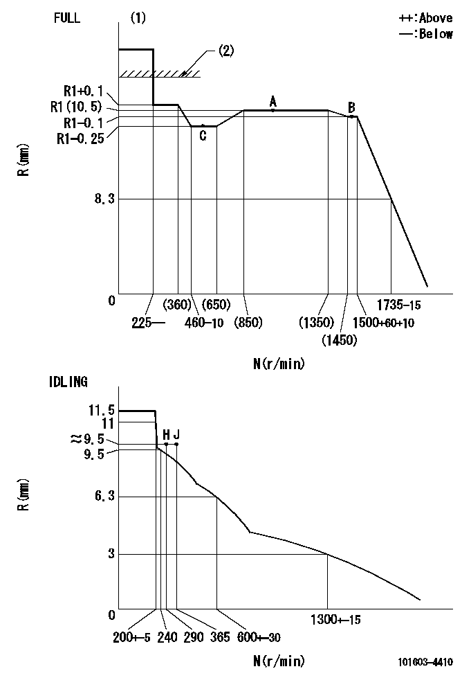
N:Pump speed
R:Rack position (mm)
(1)Torque cam stamping: T1
(2)RACK LIMIT: RAL
----------
T1=B51 RAL=13.5+0.2mm
----------
----------
T1=B51 RAL=13.5+0.2mm
----------
Speed control lever angle

F:Full speed
I:Idle
(1)Use the hole at R = aa
(2)Stopper bolt set position 'H'
----------
aa=35mm
----------
a=40deg+-5deg b=33deg+-3deg
----------
aa=35mm
----------
a=40deg+-5deg b=33deg+-3deg
Stop lever angle

N:Pump normal
S:Stop the pump.
----------
----------
a=25deg+-5deg b=40deg+-5deg
----------
----------
a=25deg+-5deg b=40deg+-5deg
0000001501 ACS

(A) Set screw
(B) Push rod 1
(C) Push rod 2
(D) Cover
1. Aneroid compensator unit adjustment
(1)Select the push rod 2 to obtain L2.
(2)Screw in (A) to obtain L1.
2. Adjustment when mounting the governor.
(1)Set the speed of the pump to N1 r/min and fix the control lever at the full set position.
(2)Screw in the aneroid compensator to obtain the performance shown in the graph above.
(3)As there is hysterisis, measure when the absolute pressure drops.
(4)Hysterisis must not exceed rack position = h1.
----------
N1=1000r/min L1=(1.5)mm L2=11+-0.5mm h1=0.15mm
----------
Ra=R1(10.5)mm Rb=R1-0.5mm Pa=89.8+-2.7kPa(674+-20mmHg) Pb=70.1+-0.7kPa(526+-5mmHg) Q1=68.6+-1cm3/1000st Q2=55.2+-1.6cm3/1000st
----------
N1=1000r/min L1=(1.5)mm L2=11+-0.5mm h1=0.15mm
----------
Ra=R1(10.5)mm Rb=R1-0.5mm Pa=89.8+-2.7kPa(674+-20mmHg) Pb=70.1+-0.7kPa(526+-5mmHg) Q1=68.6+-1cm3/1000st Q2=55.2+-1.6cm3/1000st
Timing setting

(1)Pump vertical direction
(2)Position of timer's threaded hole at No 1 cylinder's beginning of injection
(3)B.T.D.C.: aa
(4)-
----------
aa=16deg
----------
a=(60deg)
----------
aa=16deg
----------
a=(60deg)
Information:
ACTION REQUIRED
Before completing the attached Rework Procedure, review the safety actions in the Operation and Maintenance Manual for safety information and safe working practices before starting the rework.
If the head gasket has failed replace the head gasket and the fuel injection pump.
Note - This service letter does not cover mechanical failure of the fuel pump that has resulted in cylinder head gasket failure, such as mechanical failure of the advance box due to air ingress.
The 483-2328 Fuel Injection Pump has revised injection timing to reduce the peak cylinder pressure in the engine. It is essential that the pump is installed as per the Disassembly and Assembly, "Fuel Injection Pump - Install - Delphi DP210" to achieve the desired fuel injection timing.
SERVICE CLAIM ALLOWANCES
Product smu/age whichever comes first Caterpillar Dealer Suggested Customer Suggested
Parts % Labor Hrs% Parts % Labor Hrs% Parts % Labor Hrs%
0-6000 hrs,
0-108 mo 100.0% 100.0% 0.0% 0.0% 0.0% 0.0%
This is a 13.0-hour job
A maximum of $100 will be allowed for machining of cylinder head face to achieve required surface finish after failure.
PARTS DISPOSITION
Handle the parts in accordance with your Warranty Bulletin on warranty parts handling.
Rework Procedure
If the head gasket has failed follow the rework procedure for both head gasket replacement and for fuel injection pump replacement. Check that the fuel pump has not suffered a mechanical failure that has resulted in a head gasket failure, such as mechanical failure of the advance box due to air ingress. Head gasket failure due to mechanical failure of the fuel pump is not covered by this service letter.
Head gasket replacement:
Confirm the head gasket has failed through removal of the cylinder head and visual inspection of the gasket. Remove cylinder head ? refer to Disassembly and Assembly, "Cylinder Head - Remove". Confirm head gasket has failed through visual inspection, as per the images shown in Image 1.1.1.
Clean the cylinder head face and the cylinder block face to remove any deposits on the gasket sealing surface using an appropriate cleaner. Do not use abrasive materials to remove the deposits during the cleaning process to ensure that the correct surface flatness is maintained.
Inspect cylinder head for flatness and distortion. Refer to Image 1.1.2 for surface finish. Refer to System Operation Testing and Adjusting, "Cylinder Head ? Inspect" for more information. Resurface the cylinder head if required as per Testing and Adjusting, "Cylinder Head ? Inspect".
Inspect cylinder block for surface finish on the top deck of the cylinder block. Refer to Image 1.1.2 for surface finish. If the cylinder block is within specifications, install a new 258-4946 Cylinder Head Gasket. If the block is not within specification, refer to Reuse And Salvage Guidelines, SEBF8076, "Specifications to Salvage Contact Surfaces of Cylinder Blocks" for more information.
Note: A 369-3705 Cylinder Head Gasket may be required, depending on reuse and salvage guidelines.
Follow Disassembly and Assembly, "Cylinder Head ? Install" with a new gasket as per above information.
Fuel injection pump replacement:
Follow Disassembly and Assembly, "Fuel Injection Pump - Remove - Delphi DP210". Do not reuse the fuel pump.