Information injection-pump assembly
BOSCH
9 400 615 078
9400615078
ZEXEL
101603-4321
1016034321
ISUZU
1156019064
1156019064
Rating:
Service parts 101603-4321 INJECTION-PUMP ASSEMBLY:
1.
_
7.
COUPLING PLATE
8.
_
9.
_
11.
Nozzle and Holder
1-15300-104-2
12.
Open Pre:MPa(Kqf/cm2)
18.1{185}

15.
NOZZLE SET
Include in #1:
101603-4321
as INJECTION-PUMP ASSEMBLY
Include in #2:
104749-6650
as _
Cross reference number
BOSCH
9 400 615 078
9400615078
ZEXEL
101603-4321
1016034321
ISUZU
1156019064
1156019064
Zexel num
Bosch num
Firm num
Name
101603-4321
9 400 615 078
1156019064 ISUZU
INJECTION-PUMP ASSEMBLY
6BG1 K 14BE INJECTION PUMP ASSY PE6A PE
6BG1 K 14BE INJECTION PUMP ASSY PE6A PE
Calibration Data:
Adjustment conditions
Test oil
1404 Test oil ISO4113 or {SAEJ967d}
1404 Test oil ISO4113 or {SAEJ967d}
Test oil temperature
degC
40
40
45
Nozzle and nozzle holder
105780-8140
Bosch type code
EF8511/9A
Nozzle
105780-0000
Bosch type code
DN12SD12T
Nozzle holder
105780-2080
Bosch type code
EF8511/9
Opening pressure
MPa
17.2
Opening pressure
kgf/cm2
175
Injection pipe
Outer diameter - inner diameter - length (mm) mm 6-2-600
Outer diameter - inner diameter - length (mm) mm 6-2-600
Overflow valve opening pressure
kPa
157
123
191
Overflow valve opening pressure
kgf/cm2
1.6
1.25
1.95
Tester oil delivery pressure
kPa
157
157
157
Tester oil delivery pressure
kgf/cm2
1.6
1.6
1.6
Direction of rotation (viewed from drive side)
Right R
Right R
Injection timing adjustment
Direction of rotation (viewed from drive side)
Right R
Right R
Injection order
1-5-3-6-
2-4
Pre-stroke
mm
3.6
3.55
3.65
Beginning of injection position
Drive side NO.1
Drive side NO.1
Difference between angles 1
Cal 1-5 deg. 60 59.5 60.5
Cal 1-5 deg. 60 59.5 60.5
Difference between angles 2
Cal 1-3 deg. 120 119.5 120.5
Cal 1-3 deg. 120 119.5 120.5
Difference between angles 3
Cal 1-6 deg. 180 179.5 180.5
Cal 1-6 deg. 180 179.5 180.5
Difference between angles 4
Cyl.1-2 deg. 240 239.5 240.5
Cyl.1-2 deg. 240 239.5 240.5
Difference between angles 5
Cal 1-4 deg. 300 299.5 300.5
Cal 1-4 deg. 300 299.5 300.5
Injection quantity adjustment
Adjusting point
-
Rack position
11.4
Pump speed
r/min
900
900
900
Average injection quantity
mm3/st.
70.7
69.1
72.3
Max. variation between cylinders
%
0
-2.5
2.5
Basic
*
Fixing the rack
*
Standard for adjustment of the maximum variation between cylinders
*
Injection quantity adjustment_02
Adjusting point
-
Rack position
9.6+-0.5
Pump speed
r/min
260
260
260
Average injection quantity
mm3/st.
9.4
8.1
10.7
Max. variation between cylinders
%
0
-14
14
Fixing the rack
*
Standard for adjustment of the maximum variation between cylinders
*
Remarks
Adjust only variation between cylinders; adjust governor according to governor specifications.
Adjust only variation between cylinders; adjust governor according to governor specifications.
Injection quantity adjustment_03
Adjusting point
A
Rack position
R1(11.4)
Pump speed
r/min
900
900
900
Average injection quantity
mm3/st.
70.7
69.7
71.7
Basic
*
Fixing the lever
*
Injection quantity adjustment_04
Adjusting point
B
Rack position
(R1-0.4)
Pump speed
r/min
1500
1500
1500
Average injection quantity
mm3/st.
76
74.4
77.6
Fixing the lever
*
Injection quantity adjustment_05
Adjusting point
I
Rack position
-
Pump speed
r/min
150
150
150
Average injection quantity
mm3/st.
86
86
96
Fixing the lever
*
Rack limit
*
Timer adjustment
Pump speed
r/min
550--
Advance angle
deg.
0
0
0
Remarks
Start
Start
Timer adjustment_02
Pump speed
r/min
500
Advance angle
deg.
0.5
Timer adjustment_03
Pump speed
r/min
1500
Advance angle
deg.
4
3.5
4.5
Remarks
Finish
Finish
Test data Ex:
Governor adjustment
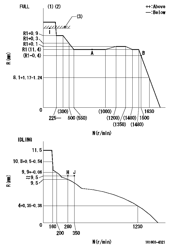
N:Pump speed
R:Rack position (mm)
(1)Torque cam stamping: T1
(2)Tolerance for racks not indicated: +-0.05mm.
(3)RACK LIMIT
----------
T1=E60
----------
----------
T1=E60
----------
Speed control lever angle
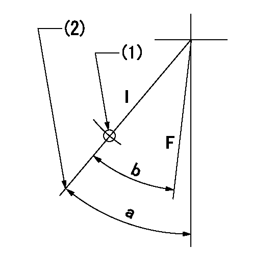
F:Full speed
I:Idle
(1)Use the hole at R = aa
(2)Stopper bolt set position 'H'
----------
aa=35mm
----------
a=42deg+-5deg b=35deg+-3deg
----------
aa=35mm
----------
a=42deg+-5deg b=35deg+-3deg
Stop lever angle

N:Pump normal
S:Stop the pump.
----------
----------
a=25deg+-5deg b=40deg+-5deg
----------
----------
a=25deg+-5deg b=40deg+-5deg
0000001501 ACS

(A) Set screw
(B) Push rod 1
(C) Push rod 2
(D) Cover
1. Aneroid compensator unit adjustment
(1)Select the push rod 2 to obtain L2.
(2)Screw in (A) to obtain L1.
2. Adjustment when mounting the governor.
(1)Set the speed of the pump to N1 r/min and fix the control lever at the full set position.
(2)Screw in the aneroid compensator to obtain the performance shown in the graph above.
(3)As there is hysterisis, measure when the absolute pressure drops.
(4)Hysterisis must not exceed rack position = h1.
----------
N1=900r/min L1=(1.5)mm L2=11+-0.5mm h1=0.15mm
----------
Ra=R1(11.4)mm Rb=R1-0.7mm Pa=89.8+-2.7kPa(674+-20mmHg) Pb=70.1+-0.7kPa(526+-5mmHg) Q1=70.7+-1cm3/1000st Q2=(59.1)cm3/1000st
----------
N1=900r/min L1=(1.5)mm L2=11+-0.5mm h1=0.15mm
----------
Ra=R1(11.4)mm Rb=R1-0.7mm Pa=89.8+-2.7kPa(674+-20mmHg) Pb=70.1+-0.7kPa(526+-5mmHg) Q1=70.7+-1cm3/1000st Q2=(59.1)cm3/1000st
Timing setting

(1)Pump vertical direction
(2)Position of timer's threaded hole at No 1 cylinder's beginning of injection
(3)B.T.D.C.: aa
(4)-
----------
aa=14deg
----------
a=(60deg)
----------
aa=14deg
----------
a=(60deg)
Information:
(1) Remove the plug in the dash and install 3T306 Starting Aid Switch (1). Connect two purple wires (2), from the wiring harness, to switch (1).(2) On machines with a bulldozer, remove two nuts (3), washers and bolts. Remove two bolts (4) and washers. Remove bracket (5) from bracket (6). (3) Put 7G6359 Box Assembly (7) in position and install two 5F4899 Bolts (8) and 5M2894 Washers. Install two S1594 Bolts (9), 5P1075 Washers and 1D4717 Nuts to hold box assembly (7) to bracket (6). Install 4M7470 Grommet in hole (A).(4) Put the wires of 6N7674 Valve Assembly (10) through hole (A) and install valve assembly (10) on box assembly (7) with two S1617 Bolts (11), 5P4116 Washers and 1D4716 Nuts. Install 7N2059 Clamp Assembly (12) with two S1617 Bolts, 5P4116 Washers and 1D4716 Nuts. Install 63801 Washer (13) on 6D1746 Bolt (14). Put bolt (14) in position in cover (15) and install L1365 Washer (16) on bolt (14). Install 3B4610 Cotter Pin (17) in bolt (14). (5) Remove the plug from the manifold and install 6N9995 Atomizer Assembly (18) as shown. The orifices of the atomizer must be toward each end of the manifold. Install 5P7907 Connector (19) in valve assembly (10). Connect 9G941 Tube (20) to atomizer assembly (18). Use 5P6314 Sleeve (21) and 5P6313 Nut (22) to connect tube (20) to connector (19). Remove the plug from the bypass elbow of the water lines group and install 6N5899 Switch (23). Connect 9G6560 Wire Assembly (24) to switch (23) and to valve assembly (10). Connect 9G6561 Wire Assembly (25) to valve assembly (10) and to the purple wire, from the starting aid switch, at the rear of the engine. Use former clips (26) to hold wire assemblies (24) and (25) in position.(6) Remove cap (27) from valve assembly (10) and install a 7N296 Cylinder Assembly. (7) For machines without bulldozer lines, remove the two bolts from the cylinder head and put 7G6359 Box Assembly (7) in position. Install two 5F4899 Bolts (8) and 5M2894 Washers. Remove the bolt from the exhaust manifold and put 3T1685 Bracket (27) in position. Install L2070 Bolt (28), 5M2894 Washer and 1D4717 Nut. Install two S1594 Bolts (9), 5P1075 Washers and 1D4717 Nuts. Install the 4M7470 Grommet in hole (A), see Step 3. Follow Steps 1, 4, 5 and 6 for installation of the group.
Have questions with 101603-4321?
Group cross 101603-4321 ZEXEL
Isuzu
Isuzu
101603-4321
9 400 615 078
1156019064
INJECTION-PUMP ASSEMBLY
6BG1
6BG1