Information injection-pump assembly
BOSCH
9 400 615 062
9400615062
ZEXEL
101603-2740
1016032740
HINO
220206020A
220206020a
Rating:
Service parts 101603-2740 INJECTION-PUMP ASSEMBLY:
1.
_
6.
COUPLING PLATE
7.
COUPLING PLATE
8.
_
9.
_
11.
Nozzle and Holder
23600-1593A
12.
Open Pre:MPa(Kqf/cm2)
21.6{220}
15.
NOZZLE SET
Cross reference number
BOSCH
9 400 615 062
9400615062
ZEXEL
101603-2740
1016032740
HINO
220206020A
220206020a
Zexel num
Bosch num
Firm num
Name
101603-2740
9 400 615 062
220206020A HINO
INJECTION-PUMP ASSEMBLY
W06D K 14BE INJECTION PUMP ASSY PE6A PE
W06D K 14BE INJECTION PUMP ASSY PE6A PE
Calibration Data:
Adjustment conditions
Test oil
1404 Test oil ISO4113 or {SAEJ967d}
1404 Test oil ISO4113 or {SAEJ967d}
Test oil temperature
degC
40
40
45
Nozzle and nozzle holder
105780-8140
Bosch type code
EF8511/9A
Nozzle
105780-0000
Bosch type code
DN12SD12T
Nozzle holder
105780-2080
Bosch type code
EF8511/9
Opening pressure
MPa
17.2
Opening pressure
kgf/cm2
175
Injection pipe
Outer diameter - inner diameter - length (mm) mm 6-2-600
Outer diameter - inner diameter - length (mm) mm 6-2-600
Overflow valve
131424-5720
Overflow valve opening pressure
kPa
255
221
289
Overflow valve opening pressure
kgf/cm2
2.6
2.25
2.95
Tester oil delivery pressure
kPa
157
157
157
Tester oil delivery pressure
kgf/cm2
1.6
1.6
1.6
Direction of rotation (viewed from drive side)
Right R
Right R
Injection timing adjustment
Direction of rotation (viewed from drive side)
Right R
Right R
Injection order
1-4-2-6-
3-5
Pre-stroke
mm
3.1
3.05
3.15
Beginning of injection position
Drive side NO.1
Drive side NO.1
Difference between angles 1
Cal 1-4 deg. 60 59.5 60.5
Cal 1-4 deg. 60 59.5 60.5
Difference between angles 2
Cyl.1-2 deg. 120 119.5 120.5
Cyl.1-2 deg. 120 119.5 120.5
Difference between angles 3
Cal 1-6 deg. 180 179.5 180.5
Cal 1-6 deg. 180 179.5 180.5
Difference between angles 4
Cal 1-3 deg. 240 239.5 240.5
Cal 1-3 deg. 240 239.5 240.5
Difference between angles 5
Cal 1-5 deg. 300 299.5 300.5
Cal 1-5 deg. 300 299.5 300.5
Injection quantity adjustment
Adjusting point
A
Rack position
8.2
Pump speed
r/min
1400
1400
1400
Average injection quantity
mm3/st.
33.7
31.7
35.7
Max. variation between cylinders
%
0
-3
3
Basic
*
Fixing the rack
*
Injection quantity adjustment_02
Adjusting point
C
Rack position
7.4+-0.5
Pump speed
r/min
500
500
500
Average injection quantity
mm3/st.
8
6.5
9.5
Max. variation between cylinders
%
0
-15
15
Fixing the rack
*
Injection quantity adjustment_03
Adjusting point
D
Rack position
-
Pump speed
r/min
100
100
100
Average injection quantity
mm3/st.
60
60
70
Fixing the lever
*
Rack limit
*
Timer adjustment
Pump speed
r/min
1100--
Advance angle
deg.
0
0
0
Remarks
Start
Start
Timer adjustment_02
Pump speed
r/min
1050
Advance angle
deg.
0.3
Timer adjustment_03
Pump speed
r/min
1400
Advance angle
deg.
1.8
1.5
2.1
Timer adjustment_04
Pump speed
r/min
-
Advance angle
deg.
4.5
4.5
4.5
Remarks
Measure the actual speed, stop
Measure the actual speed, stop
Test data Ex:
Governor adjustment
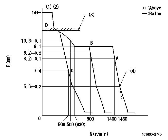
N:Pump speed
R:Rack position (mm)
(1)Target notch: K
(2)Tolerance for racks not indicated: +-0.05mm.
(3)RACK LIMIT
(4)Idle sub spring setting: L1.
----------
K=12 L1=5.6-0.5mm
----------
----------
K=12 L1=5.6-0.5mm
----------
Speed control lever angle
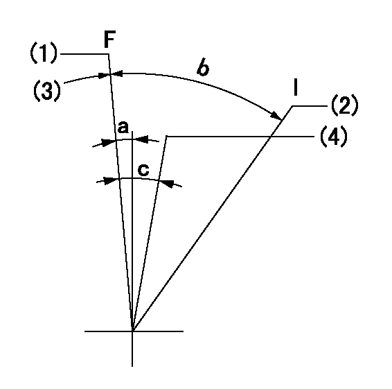
F:Full speed
I:Idle
(1)Set the pump speed at aa
(2)Stopper bolt setting
(3)Stopper bolt setting
(4)When pump speed set at bb
----------
aa=1400r/min bb=900r/min
----------
a=10deg+-5deg b=22deg+-5deg c=12deg+-5deg
----------
aa=1400r/min bb=900r/min
----------
a=10deg+-5deg b=22deg+-5deg c=12deg+-5deg
Stop lever angle

N:Pump normal
S:Stop the pump.
(1)Normal
(2)Rack position aa or less, pump speed bb
----------
aa=6.9mm bb=0r/min
----------
a=27deg+-5deg b=53deg+-5deg
----------
aa=6.9mm bb=0r/min
----------
a=27deg+-5deg b=53deg+-5deg
Timing setting

(1)Pump vertical direction
(2)Position of gear's standard threaded hole at No 1 cylinder's beginning of injection
(3)-
(4)-
----------
----------
a=(70deg)
----------
----------
a=(70deg)
Information:
Typical Example1. Remove bolts (1) and cover (2). Remove bolts (3) and cover (4).
Typical Example2. Remove bolts (5) and adapter (6). Be sure that gear stays in place. Remove bolts (7) and cover (8). Keep gear in place.
Typical Example3. Remove gears (9) and crankshaft gear (10). Remove bolts (11) and idler gear (12) with retainer. Remove bolts (13) and idler gear (14) with retainer.
Typical Example4. Secure strap and a hoist to housing (15). Remove hose assembly (16) and small bolts (17) and large bolts (18). 5. Remove bolts (19) that connect housing to oil pan (20). Remove housing from cylinder block. The weight of housing is approximately 105 kg (230 lb). 6. Check O-ring seal (21) and bearing (22) on adapter and replace if necessary. 7. Check bearing (23) and O-ring seal (24) on cover and replace if necessary. 8. Remove retainer (25) from gear (9) and check bearings (26) and replace if necessary. The following steps are for the installation of the flywheel housing.9. Thoroughly clean the contact surfaces of the cylinder block and flywheel housing. Install a new gasket between the flywheel housing and the cylinder clock.10. Secure strap and a hoist to the flywheel housing, put flywheel housing in position on the cylinder block. 11. Install the bolts that hold the flywheel housing to the cylinder block. Tighten bolts 1 thru 22 in number sequence to a torque of 40 10 N m (30 7 lb ft). Tighten bolts 1 thru 9 in number sequence again to a torque of 135 20 N m (100 15 lb ft). Tighten bolts 10 thru 22 in number sequence again to a torque of 55 10 N m (40 7 lb ft).12. Install bolts that connect housing to oil pan.13. Cut flywheel housing gasket off even with the cylinder block surface. Remove excess sealant.End By:a. install crankshaft rear seal and wear sleeveb. install starting motor
Have questions with 101603-2740?
Group cross 101603-2740 ZEXEL
Hino
101603-2740
9 400 615 062
220206020A
INJECTION-PUMP ASSEMBLY
W06D
W06D