Information injection-pump assembly
ZEXEL
101603-2690
1016032690

Rating:
Cross reference number
ZEXEL
101603-2690
1016032690
Zexel num
Bosch num
Firm num
Name
101603-2690
INJECTION-PUMP ASSEMBLY
Calibration Data:
Adjustment conditions
Test oil
1404 Test oil ISO4113 or {SAEJ967d}
1404 Test oil ISO4113 or {SAEJ967d}
Test oil temperature
degC
40
40
45
Nozzle and nozzle holder
105780-8140
Bosch type code
EF8511/9A
Nozzle
105780-0000
Bosch type code
DN12SD12T
Nozzle holder
105780-2080
Bosch type code
EF8511/9
Opening pressure
MPa
17.2
Opening pressure
kgf/cm2
175
Injection pipe
Outer diameter - inner diameter - length (mm) mm 6-2-600
Outer diameter - inner diameter - length (mm) mm 6-2-600
Overflow valve
134424-0920
Overflow valve opening pressure
kPa
162
147
177
Overflow valve opening pressure
kgf/cm2
1.65
1.5
1.8
Tester oil delivery pressure
kPa
157
157
157
Tester oil delivery pressure
kgf/cm2
1.6
1.6
1.6
Direction of rotation (viewed from drive side)
Right R
Right R
Injection timing adjustment
Direction of rotation (viewed from drive side)
Right R
Right R
Injection order
1-4-2-6-
3-5
Pre-stroke
mm
3.45
3.42
3.48
Beginning of injection position
Drive side NO.1
Drive side NO.1
Difference between angles 1
Cal 1-4 deg. 60 59.75 60.25
Cal 1-4 deg. 60 59.75 60.25
Difference between angles 2
Cyl.1-2 deg. 120 119.75 120.25
Cyl.1-2 deg. 120 119.75 120.25
Difference between angles 3
Cal 1-6 deg. 180 179.75 180.25
Cal 1-6 deg. 180 179.75 180.25
Difference between angles 4
Cal 1-3 deg. 240 239.75 240.25
Cal 1-3 deg. 240 239.75 240.25
Difference between angles 5
Cal 1-5 deg. 300 299.75 300.25
Cal 1-5 deg. 300 299.75 300.25
Injection quantity adjustment
Adjusting point
A
Rack position
9.9
Pump speed
r/min
800
800
800
Average injection quantity
mm3/st.
45.6
43.6
47.6
Max. variation between cylinders
%
0
-3
3
Basic
*
Fixing the lever
*
Injection quantity adjustment_02
Adjusting point
C
Rack position
7.9+-0.5
Pump speed
r/min
310
310
310
Average injection quantity
mm3/st.
15
13.5
16.5
Max. variation between cylinders
%
0
-15
15
Fixing the rack
*
Injection quantity adjustment_03
Adjusting point
D
Rack position
-
Pump speed
r/min
100
100
100
Average injection quantity
mm3/st.
85
85
95
Fixing the lever
*
Rack limit
*
Timer adjustment
Pump speed
r/min
900--
Advance angle
deg.
0
0
0
Remarks
Start
Start
Timer adjustment_02
Pump speed
r/min
850
Advance angle
deg.
0.3
Timer adjustment_03
Pump speed
r/min
1050
Advance angle
deg.
1.5
1.2
1.8
Remarks
Finish
Finish
Test data Ex:
Governor adjustment
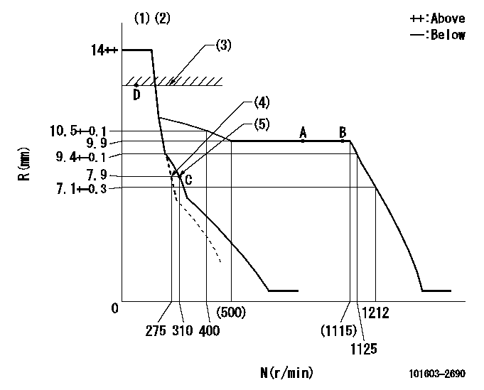
N:Pump speed
R:Rack position (mm)
(1)Target notch: K
(2)Tolerance for racks not indicated: +-0.05mm.
(3)RACK LIMIT
(4)Main spring setting
(5)Set idle sub-spring
----------
K=15
----------
----------
K=15
----------
Speed control lever angle
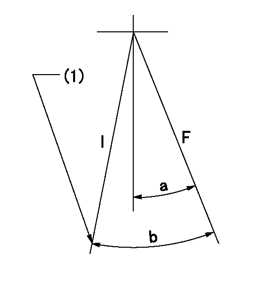
F:Full speed
I:Idle
(1)Stopper bolt setting
----------
----------
a=12deg+-5deg b=19deg+-5deg
----------
----------
a=12deg+-5deg b=19deg+-5deg
Stop lever angle
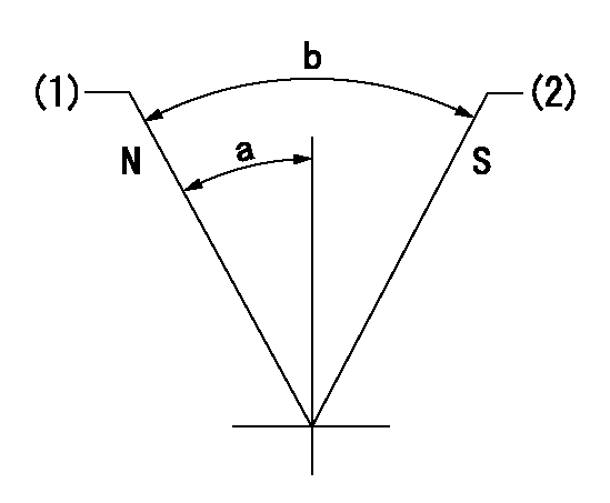
N:Pump normal
S:Stop the pump.
(1)Normal
(2)Rack position aa or less, pump speed bb
----------
aa=7.4mm bb=0r/min
----------
a=27deg+-5deg b=53deg+-5deg
----------
aa=7.4mm bb=0r/min
----------
a=27deg+-5deg b=53deg+-5deg
Timing setting

(1)Pump vertical direction
(2)Position of gear's standard threaded hole at No 1 cylinder's beginning of injection
(3)-
(4)-
----------
----------
a=(70deg)
----------
----------
a=(70deg)
Information:
(1) Inside diameter of rocker arm ... 19.063 to 19.101 mm (0.7505 to 0.7520 in) Rocker arm clearance on rocker shaft ... 0.030 to 0.089 mm (0.0012 to 0.0035 in)Maximum permissible clearance ... 0.13 mm (0.005 in)(2) Diameter of rocker shaft ... 19.012 to 19.037 mm (0.7485 to 0.7495 in)(3) Install seal (3) in cylinder head before rocker shaft is installed.(4) Length of push rods ... 270.46 to 271.98 mm (10.648 to 10.708 in) Diameter of push rods ... 7.87 to 7.92 mm (0.310 to 0.312 in)(5) End play of camshaft (new) ... 0.10 to 0.41 mm (0.004 to 0.016 in) Maximum permissible end play (worn) ... 0.51 mm (0.020 in)(6) Torque for bolt that holds camshaft gear on camshaft ... 70 N m (50 lb ft)(7) Camshaft thrust washer:A new cylinder block, camshaft and thrust washer have been introduced on the 4.236 engine. The thrust washer recess in the new block is deeper. The thrust washer thickness remains the same. The change became effective at engine serial number LD----U106654N and up. See General Information in Systems Operation for the engine serial number location.Outside diameter ... 72.95 to 73.00 mm (2.872 to 2.874 in)Cylinder block recess diameter for thrust washer ... 73.03 to 73.28 mm (2.875 to 2.885 in)Clearance of thrust washer in recess ... 0.03 mm to 0.33 mm (0.001 to 0.013 in)Inside diameter of thrust washer ... 44.45 mm (1.750 in)Thickness of thrust washer ... 5.47 to 5.54 mm (0.216 to 0.218 in) The recess in the cylinder block is deeper for current models.Earlier Models: Cylinder block recess depth for thrust washer ... 4.75 to 4.83 mm (0.187 to 0.190 in)Projection of thrust washer above cylinder block front face ... 0.66 to 0.79 mm (0.026 to 0.031 in)Current Models: Cylinder block recess depth for thrust washer ... 5.41 to 5.49 mm (0.213 to 0.216 in)Projection of thrust washer above cylinder block front face ... 0.00 to 0.13 mm (0.000 to 0.005 in)(8) Diameter of camshaft journals: No. 1 journal ... 50.710 to 50.737 mm (1.9965 to 1.9975 in)Minimum permissible diameter ... 50.660 mm (1.9945 in)No. 2 journal ... 50.457 to 50.483 mm (1.9865 to 1.9875 in)Minimum permissible diameter ... 50.406 mm (1.9845 in)No. 3 journal ... 49.949 to 49.975 mm (1.9665 to 1.9675 in)Minimum permissible diameter ... 49.898 mm (1.9645 in)(See topic Cylinder Block for camshaft bore specifications).(9) Tappet (valve lifter): Length ... 75.4063 mm (2.96875 in)Shank diameter ... 18.987 to 19.012 mm (0.7475 to 0.7485 in)Diameter of bore in block for tappet ... 19.050 to 19.083 mm (0.7500 to 0.7513 in)Running clearance between tappet and block ... 0.038 to 0.097 mm (0.0015 to 0.0038 in)Foot diameter ... 30.163 mm (1.1875 in) Camshaft lobe height:1. Measure base circle (C).2. Add lobe lift (A) to base circle measurement. Camshaft lobe lift (A) is ... 7.62 to 7.70
Have questions with 101603-2690?
Group cross 101603-2690 ZEXEL
Hino
Hino
Hino
Hino
Hino
101603-2690
INJECTION-PUMP ASSEMBLY