Information injection-pump assembly
BOSCH
9 400 612 495
9400612495
ZEXEL
101603-2671
1016032671
HINO
220205680A
220205680a
Rating:
Service parts 101603-2671 INJECTION-PUMP ASSEMBLY:
1.
_
7.
COUPLING PLATE
8.
_
9.
_
11.
Nozzle and Holder
23600-2710A
12.
Open Pre:MPa(Kqf/cm2)
17.7{180}
15.
NOZZLE SET
Include in #1:
101603-2671
as INJECTION-PUMP ASSEMBLY
Include in #2:
104749-6960
as _
Cross reference number
BOSCH
9 400 612 495
9400612495
ZEXEL
101603-2671
1016032671
HINO
220205680A
220205680a
Zexel num
Bosch num
Firm num
Name
101603-2671
9 400 612 495
220205680A HINO
INJECTION-PUMP ASSEMBLY
H07C-T K 14BF INJECTION PUMP ASSY PE6AD PE
H07C-T K 14BF INJECTION PUMP ASSY PE6AD PE
Calibration Data:
Adjustment conditions
Test oil
1404 Test oil ISO4113 or {SAEJ967d}
1404 Test oil ISO4113 or {SAEJ967d}
Test oil temperature
degC
40
40
45
Nozzle and nozzle holder
105780-8140
Bosch type code
EF8511/9A
Nozzle
105780-0000
Bosch type code
DN12SD12T
Nozzle holder
105780-2080
Bosch type code
EF8511/9
Opening pressure
MPa
17.2
Opening pressure
kgf/cm2
175
Injection pipe
Outer diameter - inner diameter - length (mm) mm 6-2-600
Outer diameter - inner diameter - length (mm) mm 6-2-600
Overflow valve
134424-0920
Overflow valve opening pressure
kPa
162
147
177
Overflow valve opening pressure
kgf/cm2
1.65
1.5
1.8
Tester oil delivery pressure
kPa
157
157
157
Tester oil delivery pressure
kgf/cm2
1.6
1.6
1.6
Direction of rotation (viewed from drive side)
Right R
Right R
Injection timing adjustment
Direction of rotation (viewed from drive side)
Right R
Right R
Injection order
1-4-2-6-
3-5
Pre-stroke
mm
4.8
4.77
4.83
Beginning of injection position
Drive side NO.1
Drive side NO.1
Difference between angles 1
Cal 1-4 deg. 60 59.75 60.25
Cal 1-4 deg. 60 59.75 60.25
Difference between angles 2
Cyl.1-2 deg. 120 119.75 120.25
Cyl.1-2 deg. 120 119.75 120.25
Difference between angles 3
Cal 1-6 deg. 180 179.75 180.25
Cal 1-6 deg. 180 179.75 180.25
Difference between angles 4
Cal 1-3 deg. 240 239.75 240.25
Cal 1-3 deg. 240 239.75 240.25
Difference between angles 5
Cal 1-5 deg. 300 299.75 300.25
Cal 1-5 deg. 300 299.75 300.25
Injection quantity adjustment
Adjusting point
A
Rack position
10.8
Pump speed
r/min
950
950
950
Average injection quantity
mm3/st.
142.5
141
144
Max. variation between cylinders
%
0
-3.5
3.5
Basic
*
Fixing the lever
*
Boost pressure
kPa
37.3
37.3
Boost pressure
mmHg
280
280
Injection quantity adjustment_02
Adjusting point
C
Rack position
5.9+-0.5
Pump speed
r/min
435
435
435
Average injection quantity
mm3/st.
8.5
7.5
9.5
Max. variation between cylinders
%
0
-10
10
Fixing the rack
*
Boost pressure
kPa
0
0
0
Boost pressure
mmHg
0
0
0
Injection quantity adjustment_03
Adjusting point
E
Rack position
-
Pump speed
r/min
100
100
100
Average injection quantity
mm3/st.
135
135
145
Fixing the lever
*
Boost pressure
kPa
0
0
0
Boost pressure
mmHg
0
0
0
Rack limit
*
Boost compensator adjustment
Pump speed
r/min
600
600
600
Rack position
R1-1.4
Boost pressure
kPa
9.3
8
10.6
Boost pressure
mmHg
70
60
80
Boost compensator adjustment_02
Pump speed
r/min
600
600
600
Rack position
R1(10.8)
Boost pressure
kPa
24
17.3
30.7
Boost pressure
mmHg
180
130
230
Timer adjustment
Pump speed
r/min
900--
Advance angle
deg.
0
0
0
Remarks
Start
Start
Timer adjustment_02
Pump speed
r/min
850
Advance angle
deg.
0.3
Timer adjustment_03
Pump speed
r/min
950
Advance angle
deg.
0.7
0.4
1
Remarks
Finish
Finish
Test data Ex:
Governor adjustment
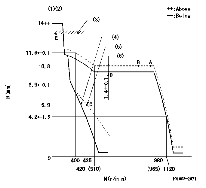
N:Pump speed
R:Rack position (mm)
(1)Notch fixed: K
(2)Tolerance for racks not indicated: +-0.05mm.
(3)RACK LIMIT
(4)Main spring setting
(5)Set idle sub-spring
(6)Boost compensator stroke
----------
K=13
----------
----------
K=13
----------
Speed control lever angle

F:Full speed
I:Idle
(1)Stopper bolt setting
----------
----------
a=(5deg)+-5deg b=(17deg)+-5deg
----------
----------
a=(5deg)+-5deg b=(17deg)+-5deg
Stop lever angle

N:Pump normal
S:Stop the pump.
(1)Pump speed aa and rack position bb (to be sealed at delivery)
(2)Normal
----------
aa=0r/min bb=1-0.5mm
----------
a=21deg+-5deg b=(55deg)
----------
aa=0r/min bb=1-0.5mm
----------
a=21deg+-5deg b=(55deg)
Timing setting

(1)Pump vertical direction
(2)Coupling's key groove position at No 1 cylinder's beginning of injection
(3)-
(4)-
----------
----------
a=(50deg)
----------
----------
a=(50deg)
Information:
Cylinder Heads Without Guides Cylinder Heads With Guides New cylinder heads have been introduced on the 4.236 engine. The new heads have replaceable valve guides. The differences between the earlier and current heads are explained below. The change became effective at engine number LD---U040236M and up. See General Information in Systems Operation for the engine serial number location.Double valve springs:(1) Outer spring: Length under test force ... 45.22 mm (1.780 in)Test force ... 178 9 N (40 2 lb)(Damper coils of spring go toward cylinder head).(2) Inner spring: Length under test force ... 39.70 mm (1.563 in)Test force ... 69 4 N (15.4 1 lb)(Damper coils of spring go toward cylinder head).Single valve springs (not shown). Length under test force ... 41.4 mm (1.63 in)Test force ... 251 13 N (56.4 3 lb)(No damper coils).Cylinder Heads Without Removable Guides
(3) Exhaust valve stem diameter ... 9.449 to 9.469 mm (0.372 to 0.3728 in) Valves are available in stem oversizes of 0.08, 0.38 and 0.76 mm (0.003, .015 and .030 in).Exhaust valve overall length ... 123.11 to 123.52 mm (4.847 to 4.863 in)Bore in cylinder head for valve ... 9.506 to 9.531 mm (0.3743 to 0.3752 in)Clearance between valve stem and bore ... 0.0368 to 0.0826 mm (0.00145 to 0.00325 in)Maximum permissible clearance between valve stem and bore ... 0.15 mm (0.006 in)(4) Intake valve stem diameter ... 9.462 to 9.487 mm (0.3725 to 0.3735 in) Valves are available in stem oversizes of 0.08, 0.38, and 0.76 mm (0.003, .015 and .030 in).Intake valve overall length ... 122.71 to 123.11 mm (4.831 to 4.847 in)Bore in cylinder head for valve ... 9.506 to 9.531 mm (0.3743 to 0.3752 in)Clearance between valve stem and bore ... 0.0191 to 0.0699 mm (0.00075 to 0.00275 in)Maximum permissible clearance between valve stem and bore ... 0.13 mm (0.005 in)Cylinder Heads With Removable Guides
(5) Valve guides: Inside diameter ... 9.53 to 9.55 mm (0.375 to 0.376 in)Outside diameter ... 15.900 to 15.913 mm (0.6260 to 0.6265 in)Parent bore diameter in cylinder head for valve guide ... 15.875 to 15.888 mm (0.6250 to 0.6255 in)Interference fit of guide in cylinder head ... 0.005 to 0.046 mm (0.0002 to 0.0018 in)Overall length of guide:Intake ... 57.94 mm (2.281 in)Exhaust ... 61.913 mm (2.4375 in)Projection of guide above valve spring recess ... 15.09 mm (0.594 in)(6) Exhaust valve stem diameter ... 9.449 to 9.468 mm (0.3720 to 0.3728 in) Clearance of valve in guide ... 0.058 to 0.102 mm (0.0023 to 0.0040 in)Maximum
Have questions with 101603-2671?
Group cross 101603-2671 ZEXEL
Hino
Hino
Hino
Hino
Hino
101603-2671
9 400 612 495
220205680A
INJECTION-PUMP ASSEMBLY
H07C-T
H07C-T