Information injection-pump assembly
BOSCH
9 400 611 327
9400611327
ZEXEL
101603-2663
1016032663
HINO
220205660A
220205660a

Rating:
Service parts 101603-2663 INJECTION-PUMP ASSEMBLY:
1.
_
7.
COUPLING PLATE
8.
_
9.
_
11.
Nozzle and Holder
23600-2710A
12.
Open Pre:MPa(Kqf/cm2)
17.7{180}
15.
NOZZLE SET
Include in #1:
101603-2663
as INJECTION-PUMP ASSEMBLY
Include in #2:
104749-6940
as _
Cross reference number
BOSCH
9 400 611 327
9400611327
ZEXEL
101603-2663
1016032663
HINO
220205660A
220205660a
Zexel num
Bosch num
Firm num
Name
101603-2663
9 400 611 327
220205660A HINO
INJECTION-PUMP ASSEMBLY
H07C-T K 14BF INJECTION PUMP ASSY PE6AD PE
H07C-T K 14BF INJECTION PUMP ASSY PE6AD PE
Calibration Data:
Adjustment conditions
Test oil
1404 Test oil ISO4113 or {SAEJ967d}
1404 Test oil ISO4113 or {SAEJ967d}
Test oil temperature
degC
40
40
45
Nozzle and nozzle holder
105780-8140
Bosch type code
EF8511/9A
Nozzle
105780-0000
Bosch type code
DN12SD12T
Nozzle holder
105780-2080
Bosch type code
EF8511/9
Opening pressure
MPa
17.2
Opening pressure
kgf/cm2
175
Injection pipe
Outer diameter - inner diameter - length (mm) mm 6-2-600
Outer diameter - inner diameter - length (mm) mm 6-2-600
Overflow valve
134424-0920
Overflow valve opening pressure
kPa
162
147
177
Overflow valve opening pressure
kgf/cm2
1.65
1.5
1.8
Tester oil delivery pressure
kPa
157
157
157
Tester oil delivery pressure
kgf/cm2
1.6
1.6
1.6
Direction of rotation (viewed from drive side)
Right R
Right R
Injection timing adjustment
Direction of rotation (viewed from drive side)
Right R
Right R
Injection order
1-4-2-6-
3-5
Pre-stroke
mm
4.8
4.77
4.83
Beginning of injection position
Drive side NO.1
Drive side NO.1
Difference between angles 1
Cal 1-4 deg. 60 59.75 60.25
Cal 1-4 deg. 60 59.75 60.25
Difference between angles 2
Cyl.1-2 deg. 120 119.75 120.25
Cyl.1-2 deg. 120 119.75 120.25
Difference between angles 3
Cal 1-6 deg. 180 179.75 180.25
Cal 1-6 deg. 180 179.75 180.25
Difference between angles 4
Cal 1-3 deg. 240 239.75 240.25
Cal 1-3 deg. 240 239.75 240.25
Difference between angles 5
Cal 1-5 deg. 300 299.75 300.25
Cal 1-5 deg. 300 299.75 300.25
Injection quantity adjustment
Adjusting point
A
Rack position
9.6
Pump speed
r/min
1050
1050
1050
Average injection quantity
mm3/st.
109
107
111
Max. variation between cylinders
%
0
-3.5
3.5
Basic
*
Fixing the lever
*
Boost pressure
kPa
36
36
Boost pressure
mmHg
270
270
Injection quantity adjustment_02
Adjusting point
-
Rack position
6.2+-0.5
Pump speed
r/min
360
360
360
Average injection quantity
mm3/st.
10
9
11
Max. variation between cylinders
%
0
-10
10
Fixing the rack
*
Boost pressure
kPa
0
0
0
Boost pressure
mmHg
0
0
0
Remarks
Adjust only variation between cylinders; adjust governor according to governor specifications.
Adjust only variation between cylinders; adjust governor according to governor specifications.
Injection quantity adjustment_03
Adjusting point
E
Rack position
-
Pump speed
r/min
100
100
100
Average injection quantity
mm3/st.
130
130
140
Fixing the lever
*
Boost pressure
kPa
0
0
0
Boost pressure
mmHg
0
0
0
Rack limit
*
Boost compensator adjustment
Pump speed
r/min
800
800
800
Rack position
R1-1.45
Boost pressure
kPa
5.3
4
6.6
Boost pressure
mmHg
40
30
50
Boost compensator adjustment_02
Pump speed
r/min
800
800
800
Rack position
R1(9.6)
Boost pressure
kPa
22.7
16
29.4
Boost pressure
mmHg
170
120
220
Timer adjustment
Pump speed
r/min
900--
Advance angle
deg.
0
0
0
Remarks
Start
Start
Timer adjustment_02
Pump speed
r/min
850
Advance angle
deg.
0.3
Timer adjustment_03
Pump speed
r/min
1050
Advance angle
deg.
1.5
1.2
1.8
Remarks
Finish
Finish
Test data Ex:
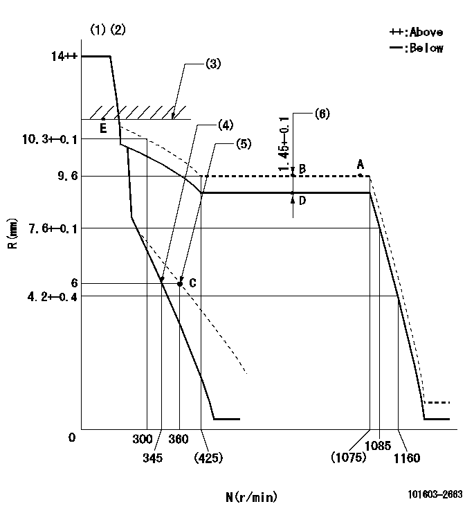
Governor adjustment

N:Pump speed
R:Rack position (mm)
(1)Target notch: K
(2)Tolerance for racks not indicated: +-0.05mm.
(3)RACK LIMIT
(4)Main spring setting
(5)Set idle sub-spring
(6)Boost compensator stroke
----------
K=6
----------
----------
K=6
----------
Speed control lever angle

F:Full speed
I:Idle
(1)Use the hole at R = aa
(2)Stopper bolt setting
----------
aa=125.4mm
----------
a=14deg+-5deg b=21deg+-5deg
----------
aa=125.4mm
----------
a=14deg+-5deg b=21deg+-5deg
Stop lever angle

N:Pump normal
S:Stop the pump.
(1)Pump speed aa and rack position bb (to be sealed at delivery)
(2)Normal
----------
aa=0r/min bb=1-0.5mm
----------
a=21deg+-5deg b=(55deg)
----------
aa=0r/min bb=1-0.5mm
----------
a=21deg+-5deg b=(55deg)
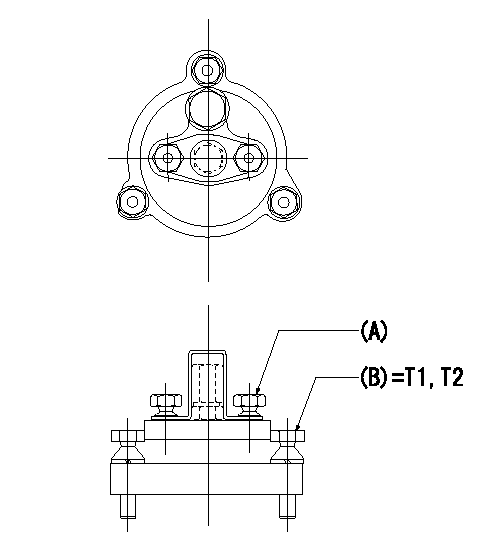
0000001501 TAMPER PROOF

Tamperproofing-equipped boost compensator cover installation procedure
(A): After adjusting the boost compensator, assemble then tighten the bolts to remove the heads.
(B): Specified torque
(1)Before adjusting the governor and the boost compensator, tighten the screw to the specified torque.
(Tightening torque T = T1 maximum)
(2)After adjusting the governor and the boost compensator, tighten to the specified torque to break off the bolt heads.
(Tightening torque T = T2)
----------
T1=2.5N-m(0.25kgf-m) T2=2.9~4.4N-m(0.3~0.45kgf-m)
----------
----------
T1=2.5N-m(0.25kgf-m) T2=2.9~4.4N-m(0.3~0.45kgf-m)
----------
Timing setting

(1)Pump vertical direction
(2)Coupling's key groove position at No 1 cylinder's beginning of injection
(3)-
(4)-
----------
----------
a=(50deg)
----------
----------
a=(50deg)
Information:
Start By:a. remove all turbochargersb. remove crankshaft rear seal and wear sleeve 1. Disconnect connector (1). 2. Attach Tool (A) and fasten a hoist.3. Remove four bolts (3) and stack (2). The weight of the stack and hardware is 45 kg (100 lb). 4. Remove hose clamp (6).5. Remove five bolts (5) and support (4).6. Repeat Steps 4 and 5 for the other side of the engine. 7. Remove six bolts (7) that connect oil pan (8) to flywheel housing (9). Loosen the rest of the bolts that hold the oil pan in position. 8. Attach Tool (A) to the flywheel housing and a hoist. 9. Lift the end of the engine enough so a 1/2 in. Hardened Washer (10) can be installed on each side of the engine between the oil pan and the cylinder block.10. Install blocks under the oil pan to support the engine when the flywheel housing is removed. Lower the engine onto the blocks. 11. Remove twenty one bolts (11) and flywheel housing (9). The weight of the flywheel housing is 91 kg (200 lb).Install Flywheel Housing
1. Install two 1/2 -13 NC × 4 in. Long Guide Bolts in the cylinder block. Make sure gasket (12) is in position. The cylinder block, both sides of gasket (12) and the surface of the flywheel housing that makes contact with the gasket must not have any oil, fuel, water or gasket adhesive on them when the flywheel housing is installed on the engine.2. Install Tool (A) on the flywheel housing. Install flywheel housing (9) on the engine. The weight of the flywheel housing is approximately 91 kg (200 lb). Leave Tool (A) attached.
Torque Sequence Put 9S-3263 Thread Lock on bolts (17) through (20) before installation.3. Install the bolts that hold the flywheel housing in place.4. Use the following procedure to tighten the bolts: a. Tighten bolts 1 through 8 in number sequence to 136 14 N m (100 10 lb ft).b. Tighten bolts 9 through 20 in number sequence to 55 7 N m (41 5 lb ft).c. Again, tighten bolts 1 through 8 in number sequence to 136 14 N m (100 10 lb ft).d. Again, tighten bolts 9 through 20 in number sequence to 55 7 N m (41 5 lb ft). If a new gasket is installed, cut the ends of the gasket so it is even with the bottom of the cylinder block.5. Use Tool (A) and a hoist to lift the flywheel housing and engine enough so that the washers between the oil pan and the cylinder block can be removed. 6. Tighten the bolts that hold the oil pan to the cylinder block. Install six bolts (7) that hold oil pan (8) to flywheel housing (9). 7. Install support (4) with five bolts (5). Install clamp (6) to a torque of 7.0 1.5 N m (5 1 lb ft).8. Repeat Step (7) for the other side of the engine.
Have questions with 101603-2663?
Group cross 101603-2663 ZEXEL
Hino
Hino
Hino
Hino
101603-2663
9 400 611 327
220205660A
INJECTION-PUMP ASSEMBLY
H07C-T
H07C-T