Information injection-pump assembly
ZEXEL
101603-2662
1016032662

Rating:
Cross reference number
ZEXEL
101603-2662
1016032662
Zexel num
Bosch num
Firm num
Name
101603-2662
INJECTION-PUMP ASSEMBLY
Calibration Data:
Adjustment conditions
Test oil
1404 Test oil ISO4113 or {SAEJ967d}
1404 Test oil ISO4113 or {SAEJ967d}
Test oil temperature
degC
40
40
45
Nozzle and nozzle holder
105780-8140
Bosch type code
EF8511/9A
Nozzle
105780-0000
Bosch type code
DN12SD12T
Nozzle holder
105780-2080
Bosch type code
EF8511/9
Opening pressure
MPa
17.2
Opening pressure
kgf/cm2
175
Injection pipe
Outer diameter - inner diameter - length (mm) mm 6-2-600
Outer diameter - inner diameter - length (mm) mm 6-2-600
Overflow valve
134424-0920
Overflow valve opening pressure
kPa
162
147
177
Overflow valve opening pressure
kgf/cm2
1.65
1.5
1.8
Tester oil delivery pressure
kPa
157
157
157
Tester oil delivery pressure
kgf/cm2
1.6
1.6
1.6
Direction of rotation (viewed from drive side)
Right R
Right R
Injection timing adjustment
Direction of rotation (viewed from drive side)
Right R
Right R
Injection order
1-4-2-6-
3-5
Pre-stroke
mm
4.8
4.77
4.83
Beginning of injection position
Drive side NO.1
Drive side NO.1
Difference between angles 1
Cal 1-4 deg. 60 59.75 60.25
Cal 1-4 deg. 60 59.75 60.25
Difference between angles 2
Cyl.1-2 deg. 120 119.75 120.25
Cyl.1-2 deg. 120 119.75 120.25
Difference between angles 3
Cal 1-6 deg. 180 179.75 180.25
Cal 1-6 deg. 180 179.75 180.25
Difference between angles 4
Cal 1-3 deg. 240 239.75 240.25
Cal 1-3 deg. 240 239.75 240.25
Difference between angles 5
Cal 1-5 deg. 300 299.75 300.25
Cal 1-5 deg. 300 299.75 300.25
Injection quantity adjustment
Adjusting point
A
Rack position
9.6
Pump speed
r/min
1050
1050
1050
Average injection quantity
mm3/st.
109
107
111
Max. variation between cylinders
%
0
-3.5
3.5
Basic
*
Fixing the lever
*
Boost pressure
kPa
36
36
Boost pressure
mmHg
270
270
Injection quantity adjustment_02
Adjusting point
-
Rack position
6.2+-0.5
Pump speed
r/min
360
360
360
Average injection quantity
mm3/st.
10
9
11
Max. variation between cylinders
%
0
-10
10
Fixing the rack
*
Boost pressure
kPa
0
0
0
Boost pressure
mmHg
0
0
0
Remarks
Adjust only variation between cylinders; adjust governor according to governor specifications.
Adjust only variation between cylinders; adjust governor according to governor specifications.
Injection quantity adjustment_03
Adjusting point
E
Rack position
-
Pump speed
r/min
100
100
100
Average injection quantity
mm3/st.
130
130
140
Fixing the lever
*
Boost pressure
kPa
0
0
0
Boost pressure
mmHg
0
0
0
Rack limit
*
Boost compensator adjustment
Pump speed
r/min
800
800
800
Rack position
R1-1.45
Boost pressure
kPa
5.3
4
6.6
Boost pressure
mmHg
40
30
50
Boost compensator adjustment_02
Pump speed
r/min
800
800
800
Rack position
R1(9.6)
Boost pressure
kPa
22.7
16
29.4
Boost pressure
mmHg
170
120
220
Timer adjustment
Pump speed
r/min
900--
Advance angle
deg.
0
0
0
Remarks
Start
Start
Timer adjustment_02
Pump speed
r/min
850
Advance angle
deg.
0.3
Timer adjustment_03
Pump speed
r/min
1050
Advance angle
deg.
1.5
1.2
1.8
Remarks
Finish
Finish
Test data Ex:
Governor adjustment
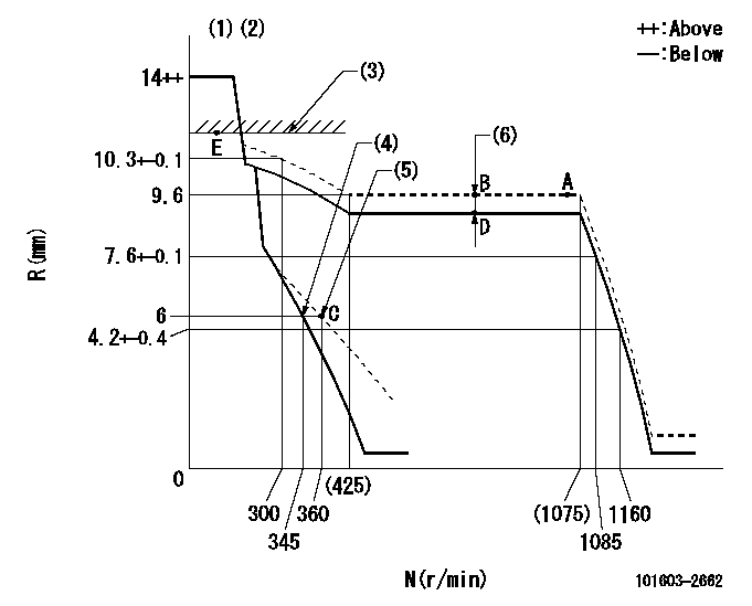
N:Pump speed
R:Rack position (mm)
(1)Target notch: K
(2)Tolerance for racks not indicated: +-0.05mm.
(3)RACK LIMIT
(4)Main spring setting
(5)Set idle sub-spring
(6)Boost compensator stroke: BCL
----------
K=6 BCL=1.45+-0.1mm
----------
----------
K=6 BCL=1.45+-0.1mm
----------
Speed control lever angle

F:Full speed
I:Idle
(1)Use the hole at R = aa
(2)Stopper bolt setting
----------
aa=125.4mm
----------
a=14deg+-5deg b=21deg+-5deg
----------
aa=125.4mm
----------
a=14deg+-5deg b=21deg+-5deg
Stop lever angle

N:Pump normal
S:Stop the pump.
(1)Pump speed aa and rack position bb (to be sealed at delivery)
(2)Normal
----------
aa=0r/min bb=1-0.5mm
----------
a=21deg+-5deg b=(55deg)
----------
aa=0r/min bb=1-0.5mm
----------
a=21deg+-5deg b=(55deg)
0000001501 TAMPER PROOF
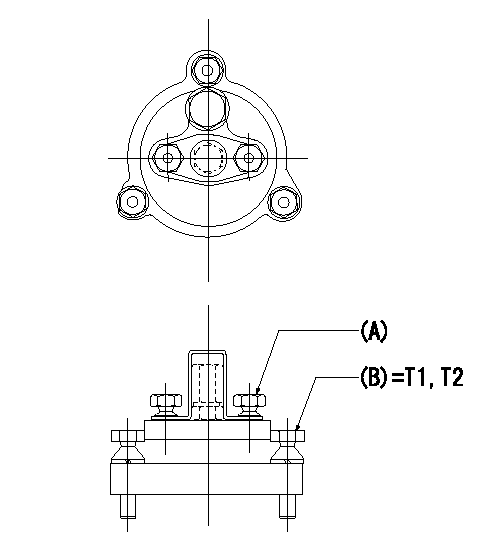
Tamperproofing-equipped boost compensator cover installation procedure
(A): After adjusting the boost compensator, assemble then tighten the bolts to remove the heads.
(B): Specified torque
(1)Before adjusting the governor and the boost compensator, tighten the screw to the specified torque.
(Tightening torque T = T1 maximum)
(2)After adjusting the governor and the boost compensator, tighten to the specified torque to break off the bolt heads.
(Tightening torque T = T2)
----------
T1=2.5N-m(0.25kgf-m) T2=2.9~4.4N-m(0.3~0.45kgf-m)
----------
----------
T1=2.5N-m(0.25kgf-m) T2=2.9~4.4N-m(0.3~0.45kgf-m)
----------
Timing setting

(1)Pump vertical direction
(2)Coupling's key groove position at No 1 cylinder's beginning of injection
(3)-
(4)-
----------
----------
a=(50deg)
----------
----------
a=(50deg)
Information:
Start By:a. remove oil pumpb. remove timing gear coverc. remove flywheel housingd. remove pistons For more detail about removal of main bearings, see the topic "Remove & Install Crankshaft Main Bearings" in this module. 1. Check each bearing cap (1) for its location on the engine. Each cap has an arrow which is toward the front of the block and a number which gives the location of that cap. Keep each bearing with the correct cap.2. Remove bearing caps No. 2 through No. 6. Remove thrust plates from No. 4 upper bearing.3. Install one of the flywheel bolts in each end of the crankshaft. Fasten a hoist to the crankshaft as shown. Remove No. 1 and No. 7 main bearing caps. Remove the crankshaft. Weight of the crankshaft is 181 kg (400 lb).
Be careful not to damage the crankshaft journals when the crankshaft is removed.
4. Remove crankshaft gear (2) with Tooling (A).5. Remove dowel and pin from crankshaft with Tooling (B).Install Crankshaft
1. Install pin (1) in the crankshaft end until it is extended from the surface a distance of 6.4 0.5 mm (.25 .02 in).2. Install dowel (2) until it is extended from the surface a distance of 4.1 0.5 mm (.16 .02 in). 3. Heat crankshaft gear (3) to a maximum temperature of 232°C (450°F). Install gear (3) on the crankshaft with groove (4) in alignment with dowel (2).4. Make sure the upper main bearings are clean. Put clean oil on the upper main bearings and journals of the crankshaft. 5. Install one of the flywheel bolts in each end of the crankshaft. Fasten a hoist to the crankshaft and put it in position in the block.
Use care to prevent damage to the crankshaft journals. Make sure the "V" mark on the crankshaft gear is in alignment with the "V" mark on the idler gear.
For more detail about installation of main bearings, see Remove And Install Crankshaft Main Bearings.6. Check the bearing clearances with Plastigage.7. Put clean engine oil on the bolts for caps No. 1 and No. 7. Install No. 1 and No. 7 caps with the bolts finger tight. Make sure the arrows on the caps are toward the front of the block. 8. Install thrust plates (5) for the No. 4 upper main bearing. Install the thrust plates with the side that has identification "BLOCK SIDE" toward the cylinder block.9. Put clean oil on the bolts for caps No. 2 through No. 6. Install caps No. 2 through No. 6 with the bolts finger tight. Make sure the arrows are toward the front of the block.
Do not use an impact wrench to tighten the bolts the additional 120 degrees.
10. Tighten the cap bolts as follows:a. Tighten the bolts on the tab end of the caps first to a torque of 260 14 N m (190
Have questions with 101603-2662?
Group cross 101603-2662 ZEXEL
Hino
Hino
Hino
101603-2662
INJECTION-PUMP ASSEMBLY