Information injection-pump assembly
ZEXEL
101603-2660
1016032660

Rating:
Cross reference number
ZEXEL
101603-2660
1016032660
Zexel num
Bosch num
Firm num
Name
101603-2660
INJECTION-PUMP ASSEMBLY
Calibration Data:
Adjustment conditions
Test oil
1404 Test oil ISO4113 or {SAEJ967d}
1404 Test oil ISO4113 or {SAEJ967d}
Test oil temperature
degC
40
40
45
Nozzle and nozzle holder
105780-8140
Bosch type code
EF8511/9A
Nozzle
105780-0000
Bosch type code
DN12SD12T
Nozzle holder
105780-2080
Bosch type code
EF8511/9
Opening pressure
MPa
17.2
Opening pressure
kgf/cm2
175
Injection pipe
Outer diameter - inner diameter - length (mm) mm 6-2-600
Outer diameter - inner diameter - length (mm) mm 6-2-600
Overflow valve
134424-0920
Overflow valve opening pressure
kPa
162
147
177
Overflow valve opening pressure
kgf/cm2
1.65
1.5
1.8
Tester oil delivery pressure
kPa
157
157
157
Tester oil delivery pressure
kgf/cm2
1.6
1.6
1.6
Direction of rotation (viewed from drive side)
Right R
Right R
Injection timing adjustment
Direction of rotation (viewed from drive side)
Right R
Right R
Injection order
1-4-2-6-
3-5
Pre-stroke
mm
4.8
4.77
4.83
Beginning of injection position
Drive side NO.1
Drive side NO.1
Difference between angles 1
Cal 1-4 deg. 60 59.75 60.25
Cal 1-4 deg. 60 59.75 60.25
Difference between angles 2
Cyl.1-2 deg. 120 119.75 120.25
Cyl.1-2 deg. 120 119.75 120.25
Difference between angles 3
Cal 1-6 deg. 180 179.75 180.25
Cal 1-6 deg. 180 179.75 180.25
Difference between angles 4
Cal 1-3 deg. 240 239.75 240.25
Cal 1-3 deg. 240 239.75 240.25
Difference between angles 5
Cal 1-5 deg. 300 299.75 300.25
Cal 1-5 deg. 300 299.75 300.25
Injection quantity adjustment
Adjusting point
A
Rack position
9.6
Pump speed
r/min
1050
1050
1050
Average injection quantity
mm3/st.
109
107
111
Max. variation between cylinders
%
0
-3.5
3.5
Basic
*
Fixing the lever
*
Boost pressure
kPa
36
36
Boost pressure
mmHg
270
270
Injection quantity adjustment_02
Adjusting point
-
Rack position
6.2+-0.5
Pump speed
r/min
360
360
360
Average injection quantity
mm3/st.
10
9
11
Max. variation between cylinders
%
0
-10
10
Fixing the rack
*
Boost pressure
kPa
0
0
0
Boost pressure
mmHg
0
0
0
Remarks
Adjust only variation between cylinders; adjust governor according to governor specifications.
Adjust only variation between cylinders; adjust governor according to governor specifications.
Boost compensator adjustment
Pump speed
r/min
800
800
800
Rack position
R1-1.45
Boost pressure
kPa
5.3
4
6.6
Boost pressure
mmHg
40
30
50
Boost compensator adjustment_02
Pump speed
r/min
800
800
800
Rack position
R1(9.6)
Boost pressure
kPa
22.7
16
29.4
Boost pressure
mmHg
170
120
220
Timer adjustment
Pump speed
r/min
900--
Advance angle
deg.
0
0
0
Remarks
Start
Start
Timer adjustment_02
Pump speed
r/min
850
Advance angle
deg.
0.3
Timer adjustment_03
Pump speed
r/min
1050
Advance angle
deg.
1.5
1.2
1.8
Remarks
Finish
Finish
Test data Ex:
Governor adjustment
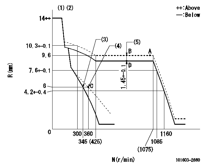
N:Pump speed
R:Rack position (mm)
(1)Target notch: K
(2)Tolerance for racks not indicated: +-0.05mm.
(3)Main spring setting
(4)Set idle sub-spring
(5)Boost compensator stroke
----------
K=6
----------
----------
K=6
----------
Speed control lever angle

F:Full speed
I:Idle
(1)Use the hole at R = aa
(2)Stopper bolt setting
----------
aa=125.4mm
----------
a=14deg+-5deg b=21deg+-5deg
----------
aa=125.4mm
----------
a=14deg+-5deg b=21deg+-5deg
Stop lever angle

N:Pump normal
S:Stop the pump.
(1)Pump speed aa and rack position bb (to be sealed at delivery)
(2)Normal
----------
aa=0r/min bb=1-0.5mm
----------
a=21deg+-5deg b=(55deg)
----------
aa=0r/min bb=1-0.5mm
----------
a=21deg+-5deg b=(55deg)
Timing setting

(1)Pump vertical direction
(2)Coupling's key groove position at No 1 cylinder's beginning of injection
(3)-
(4)-
----------
----------
a=(50deg)
----------
----------
a=(50deg)
Information:
Start By:a. remove oil pump 1. Check each connecting rod cap for its location on the crankshaft. Each cap must have a number (1) which is the same as the number on the connecting rod. Do not mix bearings.2. Turn the crankshaft until two of the pistons are at bottom center.3. Remove connecting rod caps (2). Remove the lower bearing from the connecting rod caps.4. Push the connecting rods away from the crankshaft and remove the upper bearings from the connecting rods.
Be careful not to damage the crankshaft journals. Do not turn the crankshaft while any of the connecting rod caps are removed.
5. Install the upper bearings in connecting rods. put clean engine oil on the bearings and on the crankshaft journals. Slowly pull the connecting rods on the crankshaft.6. Put clean oil on the lower bearings. Install the lower bearings in the connecting rod caps. Be sure tab (3) on the back of the bearings fits in the groove of the caps and connecting rods. 7. Check the bearing clearance with Plastigage (A) as follows:a. Put clean oil on the threads of bolts (4). Install caps (5), Tool (A) and nuts finger tight.b. Tighten each nut (6) to a torque of 80 8 N m (60 6 lb ft).c. Put a mark across the nuts and bolts. Tighten the nuts 120 degrees more. 8. Remove caps (5) and Plastigage (A). Make sure the connecting rod bearing caps are installed with their identification number in arrangement with the connecting rod number.
Do not use an impact wrench to tighten the nuts the additional 120 degrees.
9. Measure the thickness of the Plastigage to find the bearing clearance. the clearance for new bearings must be 0.071 to 0.168 mm (.0028 to .0066 in). The maximum clearance for used bearings is 0.25 mm (0.010 in).10. Install caps (5). Tighten nuts (6) to a torque of 80 8 N m (60 6 lb ft). Tighten the nuts 120 degrees more.11. Do Steps 1 through 10 for the other connecting rod bearings.End By:a. install oil pump
Have questions with 101603-2660?
Group cross 101603-2660 ZEXEL
Hino
Hino
Hino
101603-2660
INJECTION-PUMP ASSEMBLY