Information injection-pump assembly
BOSCH
9 400 611 993
9400611993
ZEXEL
101603-2632
1016032632
HINO
220205510B
220205510b

Rating:
Service parts 101603-2632 INJECTION-PUMP ASSEMBLY:
1.
_
7.
COUPLING PLATE
8.
_
9.
_
11.
Nozzle and Holder
23600-2710A
12.
Open Pre:MPa(Kqf/cm2)
17.7{180}
15.
NOZZLE SET
Include in #1:
101603-2632
as INJECTION-PUMP ASSEMBLY
Include in #2:
104740-1430
as _
Cross reference number
BOSCH
9 400 611 993
9400611993
ZEXEL
101603-2632
1016032632
HINO
220205510B
220205510b
Zexel num
Bosch num
Firm num
Name
101603-2632
9 400 611 993
220205510B HINO
INJECTION-PUMP ASSEMBLY
H07C-TE K 14BF INJECTION PUMP ASSY PE6AD PE
H07C-TE K 14BF INJECTION PUMP ASSY PE6AD PE
Calibration Data:
Adjustment conditions
Test oil
1404 Test oil ISO4113 or {SAEJ967d}
1404 Test oil ISO4113 or {SAEJ967d}
Test oil temperature
degC
40
40
45
Nozzle and nozzle holder
105780-8140
Bosch type code
EF8511/9A
Nozzle
105780-0000
Bosch type code
DN12SD12T
Nozzle holder
105780-2080
Bosch type code
EF8511/9
Opening pressure
MPa
17.2
Opening pressure
kgf/cm2
175
Injection pipe
Outer diameter - inner diameter - length (mm) mm 6-2-600
Outer diameter - inner diameter - length (mm) mm 6-2-600
Overflow valve
134424-0920
Overflow valve opening pressure
kPa
162
147
177
Overflow valve opening pressure
kgf/cm2
1.65
1.5
1.8
Tester oil delivery pressure
kPa
157
157
157
Tester oil delivery pressure
kgf/cm2
1.6
1.6
1.6
Direction of rotation (viewed from drive side)
Right R
Right R
Injection timing adjustment
Direction of rotation (viewed from drive side)
Right R
Right R
Injection order
1-4-2-6-
3-5
Pre-stroke
mm
4.8
4.77
4.83
Beginning of injection position
Drive side NO.1
Drive side NO.1
Difference between angles 1
Cal 1-4 deg. 60 59.75 60.25
Cal 1-4 deg. 60 59.75 60.25
Difference between angles 2
Cyl.1-2 deg. 120 119.75 120.25
Cyl.1-2 deg. 120 119.75 120.25
Difference between angles 3
Cal 1-6 deg. 180 179.75 180.25
Cal 1-6 deg. 180 179.75 180.25
Difference between angles 4
Cal 1-3 deg. 240 239.75 240.25
Cal 1-3 deg. 240 239.75 240.25
Difference between angles 5
Cal 1-5 deg. 300 299.75 300.25
Cal 1-5 deg. 300 299.75 300.25
Injection quantity adjustment
Adjusting point
A
Rack position
11.8
Pump speed
r/min
1300
1300
1300
Average injection quantity
mm3/st.
121.5
119.5
123.5
Max. variation between cylinders
%
0
-3.5
3.5
Basic
*
Fixing the lever
*
Boost pressure
kPa
37.3
37.3
Boost pressure
mmHg
280
280
Injection quantity adjustment_02
Adjusting point
-
Rack position
6.2+-0.5
Pump speed
r/min
550
550
550
Average injection quantity
mm3/st.
10
9
11
Max. variation between cylinders
%
0
-10
10
Fixing the rack
*
Boost pressure
kPa
0
0
0
Boost pressure
mmHg
0
0
0
Remarks
Adjust only variation between cylinders; adjust governor according to governor specifications.
Adjust only variation between cylinders; adjust governor according to governor specifications.
Boost compensator adjustment
Pump speed
r/min
800
800
800
Rack position
R1-0.7
Boost pressure
kPa
10.7
10.7
12
Boost pressure
mmHg
80
80
90
Boost compensator adjustment_02
Pump speed
r/min
800
800
800
Rack position
R1(11.8)
Boost pressure
kPa
24
24
24
Boost pressure
mmHg
180
180
180
Timer adjustment
Pump speed
r/min
1100--
Advance angle
deg.
0
0
0
Remarks
Start
Start
Timer adjustment_02
Pump speed
r/min
1050
Advance angle
deg.
0.3
Timer adjustment_03
Pump speed
r/min
1300
Advance angle
deg.
1.5
1.2
1.8
Remarks
Finish
Finish
Test data Ex:
Governor adjustment
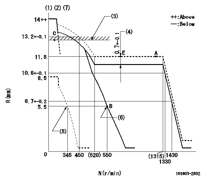
N:Pump speed
R:Rack position (mm)
(1)Target notch: K
(2)Tolerance for racks not indicated: +-0.05mm.
(3)SMA RACK LIMIT; RAL (boost pressure exceeds P1 at N = N1)
(4)Boost compensator stroke
(5)Set idle sub-spring
(6)Main spring setting
(7)Perform governor adjustment at an ambient temperature of at least 15 deg C (rack limit spring is shape memory alloy).
----------
K=13 RAL=13.1+-0.1mm N1=350r/min P1=37.3kPa(280mmHg)
----------
----------
K=13 RAL=13.1+-0.1mm N1=350r/min P1=37.3kPa(280mmHg)
----------
Speed control lever angle

F:Full speed
I:Idle
(1)Stopper bolt setting
----------
----------
a=16deg+-5deg b=24deg+-5deg
----------
----------
a=16deg+-5deg b=24deg+-5deg
Stop lever angle
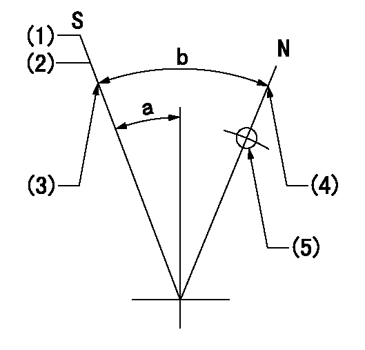
N:Pump normal
S:Stop the pump.
(1)Pump speed aa and rack position bb (to be sealed at delivery)
(2)Normal stop
(3)Stopper bolt setting
(4)Stopper bolt setting
(5)Use the hole above R = cc
----------
aa=0r/min bb=1-0.5mm cc=25mm
----------
a=13deg+-5deg b=50deg+-5deg
----------
aa=0r/min bb=1-0.5mm cc=25mm
----------
a=13deg+-5deg b=50deg+-5deg
Timing setting

(1)Pump vertical direction
(2)Coupling's key groove position at No 1 cylinder's beginning of injection
(3)-
(4)-
----------
----------
a=(50deg)
----------
----------
a=(50deg)
Information:
Start By:a. remove rocker shaft assembliesb. remove turbochargers1. Remove the valve cover bases from the cylinder head. 2. Remove sensor (7) from cylinder head (8). If necessary, remove the O-ring seal from sensor (7).3. Remove bolt and locknut (5).4. Disconnect connector (6).5. Remove bolt (4) and sensor (3). If necessary, remove the O-ring seal from sensor (3).6. Remove three bolts (2) and water lines group (1). 7. Remove bolt (9) from timing advance housing.8. Remove bolt (10) and support (11). 9. Remove the bolt and support (12). Remove the remaining ten bolts and the supports along the intake side of the cylinder head.10. Disconnect hose clamp (13) from the exhaust manifold. 11. Attach Tool (A) and fasten a hoist.12. Remove bolts (14) and remove the cylinder head. The weight of the cylinder head is approximately 172 kg (380 lb).13. Remove the head gasket and the water seals.
Do not put the cylinder head down on a flat surface. Direct injection nozzles extend out from the bottom surface of the cylinder head and will be damaged by the weight of the head.
Install Cylinder Head
1. Thoroughly clean the bottom surface of the cylinder head. Install a new head gasket and water seals. Do not use any adhesives. A new spacer plate gasket must be used when the cylinder head is installed. See the topic "Remove & Install Spacer Plate" in this module. 2. Attach Tool (D) and fasten a hoist.3. Install the cylinder head to the block. The weight of the cylinder head is approximately 172 kg (380 lb).
(1) Large bolts (3/4 inch). Put 6V-4876 Molycoat Paste Lubricant on bolt threads and between washer and underside of bolt heads. (2) Small bolts (3/8 inch). See Step 4h.4. Use the tightening sequence below to tighten the bolts that hold the cylinder head in position. a. Tighten bolts 1 through 14 in number sequence to 270 25 N m (200 20 lb ft).b. Tighten bolts 1 through 14 in number sequence to 470 20 N m (345 15 lb ft).c. Tighten bolts 1 through 14 in number sequence to 470 20 N m (345 15 lb ft).d. Install the rocker arm shafts for the engine valves and the remaining (3/4 in) bolts.e. Tighten bolts 15 through 26 in number sequence to 270 25 N m (200 20 lb ft).f. Tighten bolts 15 through 26 in number sequence to 450 20 N m (330 15 lb ft).g. Tighten bolts 15 through 26 in number sequence to 450 20 N m (330 15 lb ft).h. Tighten the thirteen small bolts (2) to a torque of 45 7 N m (33 5 lb ft). 5. Install support (12).6. Connect hose clamp (13) to exhaust manifold. 7. Install bolt (10) and support (11). Install the remaining ten bolts and the supports along the intake side of the cylinder head. Torque all twelve bolts (10) to 43 7 N m (32 5
Have questions with 101603-2632?
Group cross 101603-2632 ZEXEL
Hino
Hino
101603-2632
9 400 611 993
220205510B
INJECTION-PUMP ASSEMBLY
H07C-TE
H07C-TE