Information injection-pump assembly
ZEXEL
101603-2630
1016032630
HINO
220205510A
220205510a

Rating:
Service parts 101603-2630 INJECTION-PUMP ASSEMBLY:
1.
_
7.
COUPLING PLATE
8.
_
9.
_
11.
Nozzle and Holder
23600-2710A
12.
Open Pre:MPa(Kqf/cm2)
17.7{180}
15.
NOZZLE SET
Include in #1:
101603-2630
as INJECTION-PUMP ASSEMBLY
Include in #2:
104749-6820
as _
Cross reference number
ZEXEL
101603-2630
1016032630
HINO
220205510A
220205510a
Zexel num
Bosch num
Firm num
Name
Calibration Data:
Adjustment conditions
Test oil
1404 Test oil ISO4113 or {SAEJ967d}
1404 Test oil ISO4113 or {SAEJ967d}
Test oil temperature
degC
40
40
45
Nozzle and nozzle holder
105780-8140
Bosch type code
EF8511/9A
Nozzle
105780-0000
Bosch type code
DN12SD12T
Nozzle holder
105780-2080
Bosch type code
EF8511/9
Opening pressure
MPa
17.2
Opening pressure
kgf/cm2
175
Injection pipe
Outer diameter - inner diameter - length (mm) mm 6-2-600
Outer diameter - inner diameter - length (mm) mm 6-2-600
Overflow valve
134424-0920
Overflow valve opening pressure
kPa
162
147
177
Overflow valve opening pressure
kgf/cm2
1.65
1.5
1.8
Tester oil delivery pressure
kPa
157
157
157
Tester oil delivery pressure
kgf/cm2
1.6
1.6
1.6
Direction of rotation (viewed from drive side)
Right R
Right R
Injection timing adjustment
Direction of rotation (viewed from drive side)
Right R
Right R
Injection order
1-4-2-6-
3-5
Pre-stroke
mm
4.8
4.77
4.83
Beginning of injection position
Drive side NO.1
Drive side NO.1
Difference between angles 1
Cal 1-4 deg. 60 59.75 60.25
Cal 1-4 deg. 60 59.75 60.25
Difference between angles 2
Cyl.1-2 deg. 120 119.75 120.25
Cyl.1-2 deg. 120 119.75 120.25
Difference between angles 3
Cal 1-6 deg. 180 179.75 180.25
Cal 1-6 deg. 180 179.75 180.25
Difference between angles 4
Cal 1-3 deg. 240 239.75 240.25
Cal 1-3 deg. 240 239.75 240.25
Difference between angles 5
Cal 1-5 deg. 300 299.75 300.25
Cal 1-5 deg. 300 299.75 300.25
Injection quantity adjustment
Adjusting point
A
Rack position
11.4
Pump speed
r/min
1300
1300
1300
Average injection quantity
mm3/st.
110
108
112
Max. variation between cylinders
%
0
-3.5
3.5
Basic
*
Fixing the lever
*
Boost pressure
kPa
37.3
37.3
Boost pressure
mmHg
280
280
Injection quantity adjustment_02
Adjusting point
-
Rack position
6.2+-0.5
Pump speed
r/min
550
550
550
Average injection quantity
mm3/st.
10
9
11
Max. variation between cylinders
%
0
-10
10
Fixing the rack
*
Boost pressure
kPa
0
0
0
Boost pressure
mmHg
0
0
0
Remarks
Adjust only variation between cylinders; adjust governor according to governor specifications.
Adjust only variation between cylinders; adjust governor according to governor specifications.
Boost compensator adjustment
Pump speed
r/min
800
800
800
Rack position
R1-0.7
Boost pressure
kPa
10.7
10.7
12
Boost pressure
mmHg
80
80
90
Boost compensator adjustment_02
Pump speed
r/min
800
800
800
Rack position
R1(11.4)
Boost pressure
kPa
24
24
24
Boost pressure
mmHg
180
180
180
Timer adjustment
Pump speed
r/min
-
Advance angle
deg.
0
0
0
Remarks
Measure speed (beginning of operation).
Measure speed (beginning of operation).
Timer adjustment_02
Pump speed
r/min
-
Advance angle
deg.
1.5
1.2
1.8
Remarks
Measure the actual speed, stop
Measure the actual speed, stop
Test data Ex:
Governor adjustment
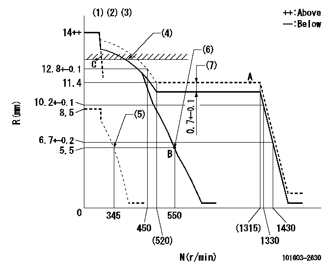
N:Pump speed
R:Rack position (mm)
(1)Target notch: K
(2)Tolerance for racks not indicated: +-0.05mm.
(3)Perform governor adjustment at an ambient temperature of at least 15 deg C (rack limit spring is shape memory alloy).
(4)SMA RACK LIMIT; RAL (boost pressure exceeds P1 at N = N1)
(5)Set idle sub-spring
(6)Main spring setting
(7)Boost compensator stroke
----------
K=14 RAL=13.1+-0.1mm N1=350r/min P1=37.3kPa(280mmHg)
----------
----------
K=14 RAL=13.1+-0.1mm N1=350r/min P1=37.3kPa(280mmHg)
----------
Speed control lever angle

F:Full speed
I:Idle
(1)Stopper bolt setting
----------
----------
a=18deg+-5deg b=24deg+-5deg
----------
----------
a=18deg+-5deg b=24deg+-5deg
Stop lever angle
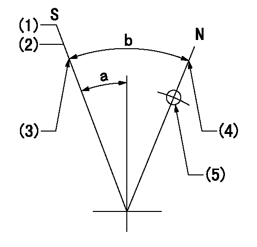
N:Pump normal
S:Stop the pump.
(1)Pump speed aa and rack position bb (to be sealed at delivery)
(2)At delivery
(3)Stopper bolt setting
(4)Stopper bolt setting
(5)Use the hole above R = cc
----------
aa=0r/min bb=1-0.5mm cc=25mm
----------
a=13deg+-5deg b=50deg+-5deg
----------
aa=0r/min bb=1-0.5mm cc=25mm
----------
a=13deg+-5deg b=50deg+-5deg
Timing setting

(1)Pump vertical direction
(2)Coupling's key groove position at No 1 cylinder's beginning of injection
(3)-
(4)-
----------
----------
a=(50deg)
----------
----------
a=(50deg)
Information:
1. Remove turbocharger return oil line (1).2. Remove two shields (2) from exhaust manifold (3). 3. Remove clamp (4).4. Remove nuts, spacers and brackets (5).5. Remove exhaust manifold (3).6. Remove the gaskets from the exhaust manifold or studs. 7. Separate section (6), sections (7) and section (8).Install Exhaust Manifold
Make sure the 2P-2333 Manifold Sealer does not get on the inside of each manifold. Damage to the turbocharger could be the result if the manifold sealer gets on the impeller on the turbocharger.
1. Apply a thin coat of 2P-2333 Manifold Sealer to the O.D. of male end of the manifold sections (7) and section (8). Coat the female ends of the manifold with clean engine oil.2. Connect sections (6), sections (7) and section (8). 3. Install 5P-3931 Anti-Seize Compound on the threads of studs (9).4. Install the gaskets on the studs. 5. Install exhaust manifold (3).6. Install nuts, spacers and brackets (5). Tighten the nuts to a torque of 38 5 N m (28 4 lb ft).7. Install clamp (4). 8. Install two shields (2) to exhaust manifold (3).9. Using a new O-ring seal at the bottom and a new gasket at the top, install turbocharger return oil line (1).