Information injection-pump assembly
BOSCH
9 400 615 048
9400615048
ZEXEL
101603-2352
1016032352
HINO
220204950B
220204950b
Rating:
Service parts 101603-2352 INJECTION-PUMP ASSEMBLY:
1.
_
6.
COUPLING PLATE
7.
COUPLING PLATE
8.
_
9.
_
11.
Nozzle and Holder
12.
Open Pre:MPa(Kqf/cm2)
19.6(200)
15.
NOZZLE SET
Cross reference number
BOSCH
9 400 615 048
9400615048
ZEXEL
101603-2352
1016032352
HINO
220204950B
220204950b
Zexel num
Bosch num
Firm num
Name
101603-2352
9 400 615 048
220204950B HINO
INJECTION-PUMP ASSEMBLY
W06E K
W06E K
Calibration Data:
Adjustment conditions
Test oil
1404 Test oil ISO4113 or {SAEJ967d}
1404 Test oil ISO4113 or {SAEJ967d}
Test oil temperature
degC
40
40
45
Nozzle and nozzle holder
105780-8140
Bosch type code
EF8511/9A
Nozzle
105780-0000
Bosch type code
DN12SD12T
Nozzle holder
105780-2080
Bosch type code
EF8511/9
Opening pressure
MPa
17.2
Opening pressure
kgf/cm2
175
Injection pipe
Outer diameter - inner diameter - length (mm) mm 6-2-600
Outer diameter - inner diameter - length (mm) mm 6-2-600
Overflow valve
134424-0920
Overflow valve opening pressure
kPa
162
147
177
Overflow valve opening pressure
kgf/cm2
1.65
1.5
1.8
Tester oil delivery pressure
kPa
157
157
157
Tester oil delivery pressure
kgf/cm2
1.6
1.6
1.6
Direction of rotation (viewed from drive side)
Right R
Right R
Injection timing adjustment
Direction of rotation (viewed from drive side)
Right R
Right R
Injection order
1-4-2-6-
3-5
Pre-stroke
mm
3.45
3.42
3.48
Beginning of injection position
Drive side NO.1
Drive side NO.1
Difference between angles 1
Cal 1-4 deg. 60 59.75 60.25
Cal 1-4 deg. 60 59.75 60.25
Difference between angles 2
Cyl.1-2 deg. 120 119.75 120.25
Cyl.1-2 deg. 120 119.75 120.25
Difference between angles 3
Cal 1-6 deg. 180 179.75 180.25
Cal 1-6 deg. 180 179.75 180.25
Difference between angles 4
Cal 1-3 deg. 240 239.75 240.25
Cal 1-3 deg. 240 239.75 240.25
Difference between angles 5
Cal 1-5 deg. 300 299.75 300.25
Cal 1-5 deg. 300 299.75 300.25
Injection quantity adjustment
Adjusting point
A
Rack position
10.5
Pump speed
r/min
1000
1000
1000
Average injection quantity
mm3/st.
59.5
57.5
61.5
Max. variation between cylinders
%
0
-3
3
Basic
*
Fixing the lever
*
Injection quantity adjustment_02
Adjusting point
B
Rack position
7.9+-0.5
Pump speed
r/min
425
425
425
Average injection quantity
mm3/st.
13.5
12
15
Max. variation between cylinders
%
0
-15
15
Fixing the rack
*
Injection quantity adjustment_03
Adjusting point
C
Rack position
-
Pump speed
r/min
100
100
100
Average injection quantity
mm3/st.
80
80
90
Fixing the lever
*
Rack limit
*
Timer adjustment
Pump speed
r/min
900--
Advance angle
deg.
0
0
0
Remarks
Start
Start
Timer adjustment_02
Pump speed
r/min
850
Advance angle
deg.
0.3
Timer adjustment_03
Pump speed
r/min
1050
Advance angle
deg.
1.5
1.2
1.8
Remarks
Finish
Finish
Test data Ex:
Governor adjustment
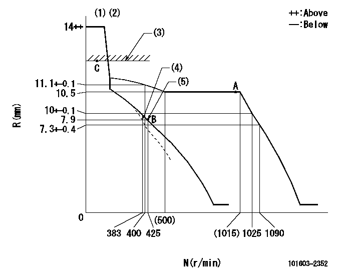
N:Pump speed
R:Rack position (mm)
(1)Target notch: K
(2)Tolerance for racks not indicated: +-0.05mm.
(3)RACK LIMIT
(4)Main spring setting
(5)Set idle sub-spring
----------
K=5
----------
----------
K=5
----------
Speed control lever angle
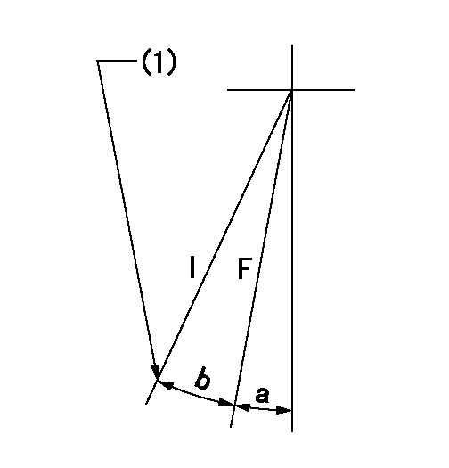
F:Full speed
I:Idle
(1)Stopper bolt setting
----------
----------
a=3deg+-5deg b=17deg+-5deg
----------
----------
a=3deg+-5deg b=17deg+-5deg
Stop lever angle
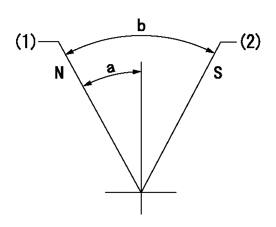
N:Pump normal
S:Stop the pump.
(1)Normal
(2)Rack position aa or less, pump speed bb
----------
aa=7.4mm bb=0r/min
----------
a=27deg+-5deg b=53deg+-5deg
----------
aa=7.4mm bb=0r/min
----------
a=27deg+-5deg b=53deg+-5deg
Timing setting

(1)Pump vertical direction
(2)Position of gear's standard threaded hole at No 1 cylinder's beginning of injection
(3)-
(4)-
----------
----------
a=(70deg)
----------
----------
a=(70deg)
Information:
Warning Operation
Two flashing warning lamps and an alarm inform the operator that: * An ether cylinder is empty.* Both ether cylinders are empty.* A noncritical fault is present.* A critical fault is present.The warning lamps and alarm can be tested by placing the ether system switch in the Test/Disable position. The warning alarm will turn ON for two seconds and the warning lamps will remain ON continuously until the switch is returned to the Auto position. If a solenoid valve is shorted to +BAT, the alarm sounds whenever the key switch is in the RUN or START position. The alarm beeps at the rate of approximately 1.3 seconds ON and 2.0 seconds OFF. The engine could be damaged if ether was injected before the engine is cranked.An Ether Cylinder Is Empty
One of the two warning lamps inform the operator when an ether cylinder is empty. The lamp flashes at the rate of 1.5 Hz (flashes per second) with equal ON and OFF times. The lamps and ether solenoid assemblies are correspondingly marked 1 and 2. When empty ether cylinder warning lamp 1 is flashing, ether cylinder 1 needs replaced. When empty ether cylinder warning lamp 2 is flashing, ether cylinder 2 needs replaced. (On 3516 engines, both ether cylinders of the set need replaced.) The lamps stop flashing when the reset switch is activated during ether cylinder replacement. The empty ether cylinder warning lamp will also flash if there is no ether cylinder installed.Both Ether Cylinders Are Empty
When both ether cylinders are empty (on 3516 engines, both ether cylinder sets), both empty ether cylinder warning lamps and the alarm are activated. Empty ether cylinder warning lamps 1 and 2 flash at the same time, at the rate of 1.5 Hz (flashes per second). The alarm also sounds, during the ether injection time, approximately 1.3 seconds ON and 2.0 seconds OFF.A Noncritical Fault Is Present
When a noncritical fault is present, both empty ether cylinder warning lamps are activated. Empty ether cylinder warning lamps 1 and 2 flash alternately (taking turns ON and OFF) at the rate of 3.0 Hz (flashes per second). The system continues to operate during a noncritical fault.A Critical Fault Is Present
When a critical fault is present. both empty ether cylinder warning lamps and the alarm are activated. Empty ether cylinder warning lamps 1 and 2 flash alternately (taking turns ON and OFF) at the rate of 3.0 Hz (flashes per second). The alarm also sounds, during the ether injection time, approximately 1.3 seconds ON and 2.0 seconds OFF. If possible, ether injections are disabled during a critical fault.Diagnostic Operation
Ether Injection Control DiagnosticsThe ether injection control has diagnostic capabilities to assist in troubleshooting. The control detects and records faults that occur to the system. During a critical fault, if possible, the control disables ether injection. During a noncritical fault, the control takes alternate action so that the system continues to function.The diagnostic display, on the ether injection control, displays a code which represents the fault that
Have questions with 101603-2352?
Group cross 101603-2352 ZEXEL
Hino
Hino
Hino
Hino
Hino
Hino
Hino
101603-2352
9 400 615 048
220204950B
INJECTION-PUMP ASSEMBLY
W06E
W06E