Information injection-pump assembly
BOSCH
9 400 610 646
9400610646
ZEXEL
101603-2340
1016032340

Rating:
Service parts 101603-2340 INJECTION-PUMP ASSEMBLY:
1.
_
7.
COUPLING PLATE
8.
_
9.
_
11.
Nozzle and Holder
23600-2710A
12.
Open Pre:MPa(Kqf/cm2)
17.7{180}
15.
NOZZLE SET
Cross reference number
BOSCH
9 400 610 646
9400610646
ZEXEL
101603-2340
1016032340
Zexel num
Bosch num
Firm num
Name
Calibration Data:
Adjustment conditions
Test oil
1404 Test oil ISO4113 or {SAEJ967d}
1404 Test oil ISO4113 or {SAEJ967d}
Test oil temperature
degC
40
40
45
Nozzle and nozzle holder
105780-8140
Bosch type code
EF8511/9A
Nozzle
105780-0000
Bosch type code
DN12SD12T
Nozzle holder
105780-2080
Bosch type code
EF8511/9
Opening pressure
MPa
17.2
Opening pressure
kgf/cm2
175
Injection pipe
Outer diameter - inner diameter - length (mm) mm 6-2-600
Outer diameter - inner diameter - length (mm) mm 6-2-600
Overflow valve
134424-0920
Overflow valve opening pressure
kPa
162
147
177
Overflow valve opening pressure
kgf/cm2
1.65
1.5
1.8
Tester oil delivery pressure
kPa
157
157
157
Tester oil delivery pressure
kgf/cm2
1.6
1.6
1.6
Direction of rotation (viewed from drive side)
Right R
Right R
Injection timing adjustment
Direction of rotation (viewed from drive side)
Right R
Right R
Injection order
1-4-2-6-
3-5
Pre-stroke
mm
4.8
4.77
4.83
Beginning of injection position
Drive side NO.1
Drive side NO.1
Difference between angles 1
Cal 1-4 deg. 60 59.75 60.25
Cal 1-4 deg. 60 59.75 60.25
Difference between angles 2
Cyl.1-2 deg. 120 119.75 120.25
Cyl.1-2 deg. 120 119.75 120.25
Difference between angles 3
Cal 1-6 deg. 180 179.75 180.25
Cal 1-6 deg. 180 179.75 180.25
Difference between angles 4
Cal 1-3 deg. 240 239.75 240.25
Cal 1-3 deg. 240 239.75 240.25
Difference between angles 5
Cal 1-5 deg. 300 299.75 300.25
Cal 1-5 deg. 300 299.75 300.25
Injection quantity adjustment
Adjusting point
A
Rack position
9.8
Pump speed
r/min
1050
1050
1050
Average injection quantity
mm3/st.
102.5
101
104
Max. variation between cylinders
%
0
-3.5
3.5
Basic
*
Fixing the lever
*
Boost pressure
kPa
37.3
37.3
Boost pressure
mmHg
280
280
Injection quantity adjustment_02
Adjusting point
-
Rack position
6.6+-0.5
Pump speed
r/min
450
450
450
Average injection quantity
mm3/st.
10
9
11
Max. variation between cylinders
%
0
-10
10
Fixing the rack
*
Boost pressure
kPa
0
0
0
Boost pressure
mmHg
0
0
0
Remarks
Adjust only variation between cylinders; adjust governor according to governor specifications.
Adjust only variation between cylinders; adjust governor according to governor specifications.
Injection quantity adjustment_03
Adjusting point
D
Rack position
-
Pump speed
r/min
100
100
100
Average injection quantity
mm3/st.
130
130
140
Fixing the lever
*
Boost pressure
kPa
0
0
0
Boost pressure
mmHg
0
0
0
Rack limit
*
Boost compensator adjustment
Pump speed
r/min
800
800
800
Rack position
R1-1.1
Boost pressure
kPa
12
12
13.3
Boost pressure
mmHg
90
90
100
Boost compensator adjustment_02
Pump speed
r/min
800
800
800
Rack position
R1(9.8)
Boost pressure
kPa
24
24
24
Boost pressure
mmHg
180
180
180
Timer adjustment
Pump speed
r/min
900--
Advance angle
deg.
0
0
0
Remarks
Start
Start
Timer adjustment_02
Pump speed
r/min
850
Advance angle
deg.
0.3
Timer adjustment_03
Pump speed
r/min
1050
Advance angle
deg.
1.5
1.2
1.8
Remarks
Finish
Finish
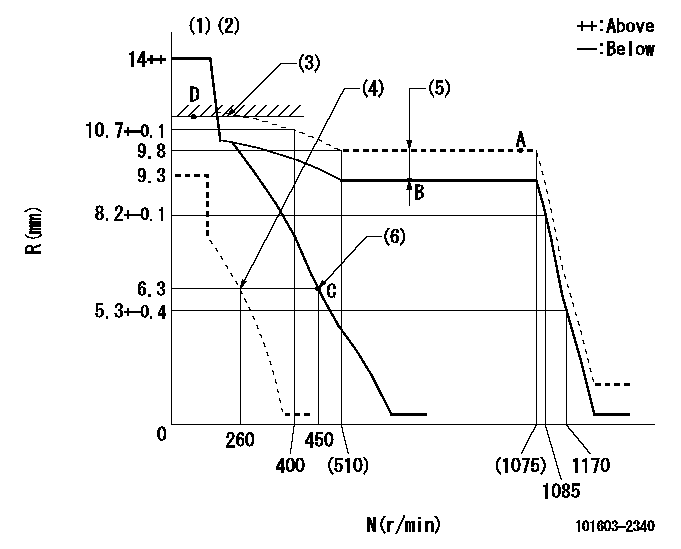
Test data Ex:
Governor adjustment

N:Pump speed
R:Rack position (mm)
(1)Target notch: K
(2)Tolerance for racks not indicated: +-0.05mm.
(3)RACK LIMIT
(4)Set idle sub-spring
(5)Boost compensator stroke: BCL
(6)Main spring setting
----------
K=12 BCL=1.1+-0.1mm
----------
----------
K=12 BCL=1.1+-0.1mm
----------
Speed control lever angle

F:Full speed
I:Idle
(1)Stopper bolt setting
----------
----------
a=6deg+-5deg b=19deg+-5deg
----------
----------
a=6deg+-5deg b=19deg+-5deg
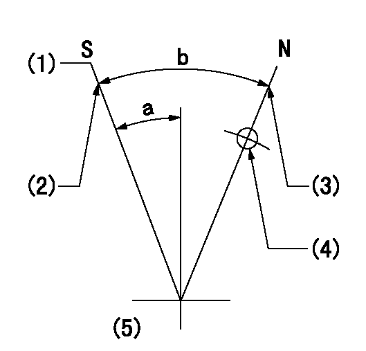
Stop lever angle

N:Pump normal
S:Stop the pump.
(1)Pump speed aa and rack position bb (to be sealed at delivery)
(2)Stopper bolt setting
(3)Stopper bolt setting
(4)Use the hole above R = cc
(5)No return spring
----------
aa=0r/min bb=1-0.5mm cc=25mm
----------
a=13deg+-5deg b=50deg+-5deg
----------
aa=0r/min bb=1-0.5mm cc=25mm
----------
a=13deg+-5deg b=50deg+-5deg
Timing setting

(1)Pump vertical direction
(2)Coupling's key groove position at No 1 cylinder's beginning of injection
(3)-
(4)-
----------
----------
a=(50deg)
----------
----------
a=(50deg)
Information:
1. Defective Upper O-ring On Unit Injectors Or Leaking Unit Injector Using the fuel priming pump, pressurize the fuel system to 689 kPa (100 psi). Check for fuel on the top deck of the cylinder head (a small amount of leakage is normal from the injector plunger barrel area after 5 minutes of constant pressure). If fuel is found, drain the fuel supply manifold. Remove each unit injector (see 3176 Vehicular Diesel Engine Disassembly and Assembly, Form No. SENR4965), and check for a defective upper O-ring on the unit injector or if the unit injector itself is leaking.A bad injector to sleeve seat causes combustion gas leakage that can damage the injector O-rings. Inspect injector hold down bolt thread depth for a minimum of 25 mm (.984 in) of thread depth in the cylinder head.Testing of the injectors must be done off of the engine. Use the 1U6661 Pop (Injector) Tester Group with a 1U6663 Injector Holding Block, and a 1U6665 Power Supply, to test the injectors. For the test procedure refer to Special Instruction, Form No. SEHS8867, Using The 1U6661 Pop (Injector) Tester. For test specifications refer to Special Instruction, Form No. SEHS8804, Unit Injector Test Specifications for 1.7 Liter Engines. Inspect and repair as necessary the sealing surface (seat) of the injector sleeve in the cylinder head when removing and installing an injector. The injector sealing surface (seat) must be free of scratches or evidence of combustion products. If it is necessary to rework (ream) or replace the sleeve use 4C4054 Tool Group and refer to Special Instruction, Form No. SEHS9246, Using The 4C4054 Unit Injector Sleeve Replacement Tool Group.2. Injector Not Seated Properly A bad injector to sleeve seat causes combustion gas leakage that can damage the injector o-rings. Inspect injector hold down bolt thread depth for a minimum of 25 mm (.984 in) of thread depth in the cylinder head.Torque fuel injector hold down bolt to 33 7 N m (24 5 lb ft). Inspect and repair as necessary the sealing surface (seat) of the injector sleeve in the cylinder head when removing and installing an injector. The injector sealing surface (seat) must be free of scratches or evidence of combustion products. If it is necessary to rework (ream) or replace the sleeve use 4C4054 Tool Group and refer to Special Instruction, Form No. SEHS9246, Using The 4C4054 Unit Injector Sleeve Replacement Tool Group.3. Crack(s) In Cylinder Head Pressurize the fuel gallery and check for crack(s). Crack(s) between the cylinder head fuel passages and passages open to the crankcase will allow fuel to enter the crankcase.4. Porosity In Cylinder HeadPressurize the fuel gallery and check for porosity. Leakage may be due to the proximity of the hole to internal fuel passages.