Information injection-pump assembly
BOSCH
9 400 610 642
9400610642
ZEXEL
101603-2280
1016032280
HINO
220204620A
220204620a
Rating:
Service parts 101603-2280 INJECTION-PUMP ASSEMBLY:
1.
_
6.
COUPLING PLATE
7.
COUPLING PLATE
8.
_
9.
_
11.
Nozzle and Holder
23600-2700A
12.
Open Pre:MPa(Kqf/cm2)
19.6{200}
15.
NOZZLE SET
Cross reference number
BOSCH
9 400 610 642
9400610642
ZEXEL
101603-2280
1016032280
HINO
220204620A
220204620a
Zexel num
Bosch num
Firm num
Name
Calibration Data:
Adjustment conditions
Test oil
1404 Test oil ISO4113 or {SAEJ967d}
1404 Test oil ISO4113 or {SAEJ967d}
Test oil temperature
degC
40
40
45
Nozzle and nozzle holder
105780-8140
Bosch type code
EF8511/9A
Nozzle
105780-0000
Bosch type code
DN12SD12T
Nozzle holder
105780-2080
Bosch type code
EF8511/9
Opening pressure
MPa
17.2
Opening pressure
kgf/cm2
175
Injection pipe
Outer diameter - inner diameter - length (mm) mm 6-2-600
Outer diameter - inner diameter - length (mm) mm 6-2-600
Overflow valve
134424-0920
Overflow valve opening pressure
kPa
162
147
177
Overflow valve opening pressure
kgf/cm2
1.65
1.5
1.8
Tester oil delivery pressure
kPa
157
157
157
Tester oil delivery pressure
kgf/cm2
1.6
1.6
1.6
Direction of rotation (viewed from drive side)
Right R
Right R
Injection timing adjustment
Direction of rotation (viewed from drive side)
Right R
Right R
Injection order
1-4-2-6-
3-5
Pre-stroke
mm
4.4
4.35
4.45
Beginning of injection position
Drive side NO.1
Drive side NO.1
Difference between angles 1
Cal 1-4 deg. 60 59.5 60.5
Cal 1-4 deg. 60 59.5 60.5
Difference between angles 2
Cyl.1-2 deg. 120 119.5 120.5
Cyl.1-2 deg. 120 119.5 120.5
Difference between angles 3
Cal 1-6 deg. 180 179.5 180.5
Cal 1-6 deg. 180 179.5 180.5
Difference between angles 4
Cal 1-3 deg. 240 239.5 240.5
Cal 1-3 deg. 240 239.5 240.5
Difference between angles 5
Cal 1-5 deg. 300 299.5 300.5
Cal 1-5 deg. 300 299.5 300.5
Injection quantity adjustment
Adjusting point
A
Rack position
11
Pump speed
r/min
700
700
700
Average injection quantity
mm3/st.
84.5
83
86
Max. variation between cylinders
%
0
-3.5
3.5
Basic
*
Fixing the lever
*
Injection quantity adjustment_02
Adjusting point
C
Rack position
6.6+-0.5
Pump speed
r/min
475
475
475
Average injection quantity
mm3/st.
8
6.5
9.5
Max. variation between cylinders
%
0
-10
10
Fixing the rack
*
Timer adjustment
Pump speed
r/min
1000--
Advance angle
deg.
0
0
0
Remarks
Start
Start
Timer adjustment_02
Pump speed
r/min
950
Advance angle
deg.
0.3
Timer adjustment_03
Pump speed
r/min
1100
Advance angle
deg.
0.7
0.4
1
Timer adjustment_04
Pump speed
r/min
-
Advance angle
deg.
1.5
1.5
1.5
Remarks
Measure the actual speed, stop
Measure the actual speed, stop
Test data Ex:
Governor adjustment
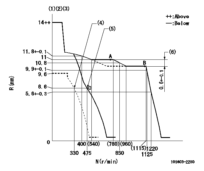
N:Pump speed
R:Rack position (mm)
(1)Target notch: K
(2)Tolerance for racks not indicated: +-0.05mm.
(3)Deliver with boost compensator not operating.
(4)Set idle sub-spring
(5)Main spring setting
(6)Rack difference between N = N1 and N = N2
----------
K=9 N1=1100r/min N2=700r/min
----------
----------
K=9 N1=1100r/min N2=700r/min
----------
Speed control lever angle
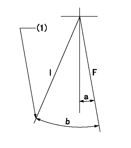
F:Full speed
I:Idle
(1)Stopper bolt setting
----------
----------
a=(6deg)+-5deg b=(24deg)+-5deg
----------
----------
a=(6deg)+-5deg b=(24deg)+-5deg
Stop lever angle

N:Pump normal
S:Stop the pump.
(1)Pump speed aa and rack position bb (to be sealed at delivery)
----------
aa=0r/min bb=1-0.5mm
----------
a=21deg+-5deg b=(55deg)
----------
aa=0r/min bb=1-0.5mm
----------
a=21deg+-5deg b=(55deg)
Timing setting

(1)Pump vertical direction
(2)Position of gear's standard threaded hole at No 1 cylinder's beginning of injection
(3)-
(4)-
----------
----------
a=(70deg)
----------
----------
a=(70deg)
Information:
(1) Diameter of rocker shaft ... 19.012 to 19.037 mm (.7485 to .7495 in.) Overall length ... 661.1938 mm (26.03125 in.)(2) Inside diameter of rocker arm ... 22.23 to 22.255 mm (.875 go .8762 in.)(3) Outside diameter of bushing ... 22.28 to 22.314 mm (.877 to .8785 in.) Interference fit of bushing in rocker lever ... 0.020 to 0.089 mm (.0008 to .0035 in.)Inside diameter of bushing (after it's reamed) ... 19.063 to 19.101 mm (.7505 to .7520 in.)Clearance of rocker shaft in bushing ... 0.03 to 0.089 mm (.001 to .0035 in.)Maximum permissible clearance ... 0.13 mm (.005 in.) See Rocker Shaft Assembly in TESTING AND ADJUSTING for proper alignment of the oil holes in the bushing and rocker lever.(4) Torque for bolts and nuts that hold rocker shaft assembly to cylinder head (tighten bolts from center outward) ... 75 N m (55 lb.ft.)(5) Install seal in cylinder head before rocker shaft assembly is installed.(6) Overall length of push rod ... 265.58 to 267.72 mm (10.456 to 10.540 in.) Shank diameter ... 7.87 to 7.92 mm (.310 to .312 in.)(7) Tappets (valve lifters): Overall length ... 75.4063 mm (2.96875 in.)Shank outside diameter ... 18.987 to 19.012 mm (.7475 to .7485 in.)Cylinder block tappet bore diameter ... 19.05 to 19.0818 mm (.750 to .75125 in.)Running clearance between tappet and block ... 0.038 to 0.0953 mm (.0015 to .00375 in.)Outside diameter of tappet foot ... 30.163 mm (1.1875 in.) (8) Diameter of camshaft journals: No. 1 journal ... 50.71 to 50.737 mm (1.9965 to 1.9975 in.)Minimum permissible diameter ... 50.660 mm (1.9945 in.)No. 2 journal ... 50.457 to 50.483 mm (1.9865 to 1.9875 in.)Minimum permissible diameter ... 50.406 mm (1.9845 in.)No. 3 journal ... 50.203 to 50.229 mm (1.9765 to 1.9775 in.)Minimum permissible diameter ... 50.152 mm (1.9745 in.)No. 4 journal ... 49.949 to 49.975 mm (1.9665 to 1.9675 in.)Minimum permissible diameter ... 48.898 mm (1.9645 in.)(See topic Cylinder Block for camshaft bore specifications.) (10) Height of the lobes of the camshaft. To get height use the procedure that follows:A. Measure base circle (11).B. Add lobe lift (9) to base circle measurement. Total is camshaft lobe height. Camshaft lobe lift (9) is:Intake ... 7.704 to 7.780 mm (.3033 to .3063 in.)Exhaust ... 7.805 to 7.881 mm (.3073 to .3103 in.)Minimum permissible height of lobes is 0.25 mm (.010 in.) less than measurement in Step B.(12) Torque for camshaft bolt ... 70 N m (50 lb.ft.)(13) End play of camshaft ... 0.10 to 0.41 mm (.004 to .016 in.) Maximum permissible end play ... 0.53 mm (.021 in.)(14) Camshaft thrust washer: Outside diameter ... 72.95 to 73.00 mm (2.872 to 2.874 in.)Cylinder block recess diameter for thrust washer ... 73.03 to 73.28 mm (2.875 to 2.885 in.)Clearance of washer in recess ... 0.03 to 0.33 mm (.001 to .013 in.)Inside diameter ... 44.45 mm (1.750 in.)Thickness ... 5.49 to 5.54 mm (.216 to .218 in.)Cylinder block