Information injection-pump assembly
BOSCH
9 400 615 045
9400615045
ZEXEL
101603-2262
1016032262
HINO
220009070B
220009070b

Rating:
Include in #1:
101603-7426
as _
Cross reference number
BOSCH
9 400 615 045
9400615045
ZEXEL
101603-2262
1016032262
HINO
220009070B
220009070b
Zexel num
Bosch num
Firm num
Name
101603-2262
9 400 615 045
220009070B HINO
INJECTION-PUMP ASSEMBLY
H07D K 14BF INJECTION PUMP ASSY PE6AD PE
H07D K 14BF INJECTION PUMP ASSY PE6AD PE
Calibration Data:
Adjustment conditions
Test oil
1404 Test oil ISO4113 or {SAEJ967d}
1404 Test oil ISO4113 or {SAEJ967d}
Test oil temperature
degC
40
40
45
Nozzle and nozzle holder
105780-8260
Bosch type code
9 430 610 133
Nozzle
105780-0120
Bosch type code
1 688 901 990
Nozzle holder
105780-2190
Opening pressure
MPa
18
Opening pressure
kgf/cm2
184
Injection pipe
Outer diameter - inner diameter - length (mm) mm 6-2-600
Outer diameter - inner diameter - length (mm) mm 6-2-600
Overflow valve
131425-0620
Overflow valve opening pressure
kPa
255
221
289
Overflow valve opening pressure
kgf/cm2
2.6
2.25
2.95
Tester oil delivery pressure
kPa
255
255
255
Tester oil delivery pressure
kgf/cm2
2.6
2.6
2.6
Direction of rotation (viewed from drive side)
Right R
Right R
Injection timing adjustment
Direction of rotation (viewed from drive side)
Right R
Right R
Injection order
1-4-2-6-
3-5
Pre-stroke
mm
4
3.97
4.03
Beginning of injection position
Drive side NO.1
Drive side NO.1
Difference between angles 1
Cal 1-4 deg. 60 59.75 60.25
Cal 1-4 deg. 60 59.75 60.25
Difference between angles 2
Cyl.1-2 deg. 120 119.75 120.25
Cyl.1-2 deg. 120 119.75 120.25
Difference between angles 3
Cal 1-6 deg. 180 179.75 180.25
Cal 1-6 deg. 180 179.75 180.25
Difference between angles 4
Cal 1-3 deg. 240 239.75 240.25
Cal 1-3 deg. 240 239.75 240.25
Difference between angles 5
Cal 1-5 deg. 300 299.75 300.25
Cal 1-5 deg. 300 299.75 300.25
Injection quantity adjustment
Adjusting point
-
Rack position
11.3
Pump speed
r/min
850
850
850
Average injection quantity
mm3/st.
93
91
95
Max. variation between cylinders
%
0
-3.5
3.5
Basic
*
Fixing the rack
*
Standard for adjustment of the maximum variation between cylinders
*
Injection quantity adjustment_02
Adjusting point
Z
Rack position
9+-0.5
Pump speed
r/min
265
265
265
Each cylinder's injection qty
mm3/st.
15
14
16
Fixing the rack
*
Standard for adjustment of the maximum variation between cylinders
*
Injection quantity adjustment_03
Adjusting point
A
Rack position
R1(11.3)
Pump speed
r/min
850
850
850
Average injection quantity
mm3/st.
93
92
94
Basic
*
Fixing the lever
*
Injection quantity adjustment_04
Adjusting point
B
Rack position
R1+0.7
Pump speed
r/min
1450
1450
1450
Average injection quantity
mm3/st.
95.5
91.5
99.5
Fixing the lever
*
Injection quantity adjustment_05
Adjusting point
D
Rack position
(R1-0.7)
Pump speed
r/min
580
580
580
Average injection quantity
mm3/st.
77.5
73.5
81.5
Fixing the lever
*
Injection quantity adjustment_06
Adjusting point
I
Rack position
-
Pump speed
r/min
100
100
100
Average injection quantity
mm3/st.
140
140
150
Fixing the lever
*
Rack limit
*
Timer adjustment
Pump speed
r/min
1100+50
Advance angle
deg.
0
0
0
Remarks
Start
Start
Timer adjustment_02
Pump speed
r/min
1450-50
Advance angle
deg.
3.5
3.2
3.8
Remarks
Finish
Finish
Test data Ex:
Governor adjustment
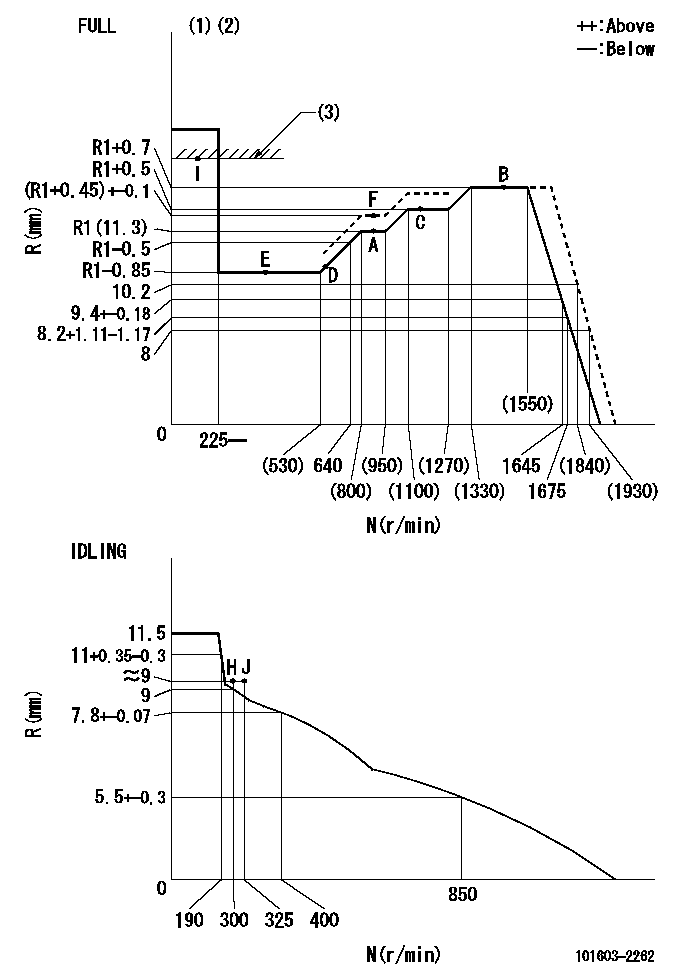
N:Pump speed
R:Rack position (mm)
(1)Torque cam stamping: T1
(2)Tolerance for racks not indicated: +-0.05mm.
(3)RACK LIMIT
----------
T1=L84
----------
----------
T1=L84
----------
Speed control lever angle
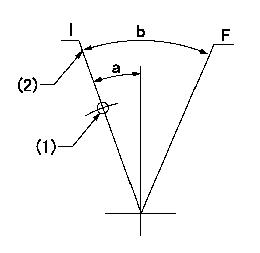
F:Full speed
I:Idle
(1)Use the hole at R = aa
(2)Stopper bolt set position 'H'
----------
aa=25.5mm
----------
a=20deg+-5deg b=40deg+-3deg
----------
aa=25.5mm
----------
a=20deg+-5deg b=40deg+-3deg
Stop lever angle
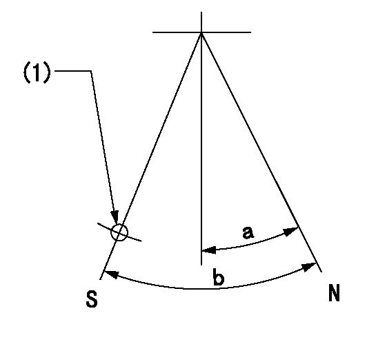
N:Pump normal
S:Stop the pump.
(1)Use the hole at R = aa
----------
aa=35mm
----------
a=14.5deg+-5deg b=40deg+-5deg
----------
aa=35mm
----------
a=14.5deg+-5deg b=40deg+-5deg
0000001501 TAMPER PROOF
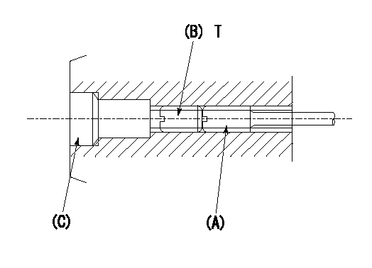
1. Method for setting tamperproof proofing
(1)Perform after governor adjustment (torque cam phase adjustment).
(2)Increase the full rack position to Ra using the load lever.
(3)Push in screw (A) to Rb.
(4)Temporarily caulk using the tip of a screwdriver
(5)Confirm that the rack at that time is at Rb .
(6)Lock using setscrew (B). (Tightening torque = T)
(7)Pressfit (C) after applying adhesive.
(8)Readjust the full rack using the load lever.
----------
Ra=(R1+0.45)+-0.1mm Rb=(R1+0.45)+-0.1mm
----------
T=4.9~7N-m(0.5~0.7Kgf-m)
----------
Ra=(R1+0.45)+-0.1mm Rb=(R1+0.45)+-0.1mm
----------
T=4.9~7N-m(0.5~0.7Kgf-m)
0000001601 AIR CYLINDER
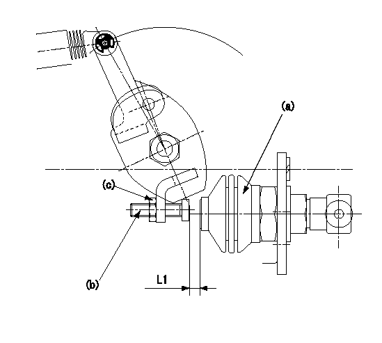
Adjustment of the air cylinder
1. Set the speed lever at the idling position.
2. Set the gap between the air cylinder (a) and the set bolt (b) to L1.
3. Set the speed at N1, apply positive pressure P1 to the air cylinder (a) and read the rack position.
4. Push set bolt (b) out and tighten nut (c) at N1 when the rack position is R1.
5. Apply positive pressure several times and confirm that the lever returns to the idle position at positive pressure P2.
6. Confirm that the rack position is R1 at positive pressure P1.
----------
L1=(8)mm R1=8.8+-0.1mm N1=475r/min P1=392+98kPa(4+1kgf/cm2) P2=0kPa(0kgf/cm2)
----------
----------
L1=(8)mm R1=8.8+-0.1mm N1=475r/min P1=392+98kPa(4+1kgf/cm2) P2=0kPa(0kgf/cm2)
----------
Timing setting

(1)Pump vertical direction
(2)Coupling's key groove position at No 1 cylinder's beginning of injection
(3)-
(4)-
----------
----------
a=(50deg)
----------
----------
a=(50deg)
Information:
(1) Outer spring: Length under test force ... 27.4 mm (1.08 in.)Test force ... 180 9 N (40 2 lb.)Free length after test ... 45.2 mm (1.78 in.)(Damper coils of spring go toward cylinder head.)(2) Inner spring: Length under test force ... 23.88 mm (.940 in.)Test force ... 69 9 N (15.4 2 lb.)Free length after test ... 39.6 mm (1.56 in.)(Damper coils of spring go toward cylinder head.)(3) Valve guides: Inside diameter ... 9.507 to 9.543 mm (.3743 to .3757 in.)Outside diameter ... 15.921 to 15.933 mm (.6268 to .6273 in.)Parent bore diameter in cylinder head for valve guide ... 15.867 to 15.893 mm (.6247 to .6257 in.)Interference fit of guide in cylinder head ... 0.028 to 0.066 mm (.0011 to .0026 in.)Overall length of guide: Intake ... 57.94 mm (2.281 in.)Exhaust ... 61.11 mm (2.406 in.)Projection of guide above valve spring recess ... 15.09 mm (.594 in.)(4) Intake valve: Valve stem diameter ... 9.42 to 9.45 mm (.371 to .372 in.)Clearance of valve in guide ... 0.058 to 0.119 mm (.0023 to .0047 in.)Maximum permissible clearance of valve in guide ... 0.13 mm (.005 in.)Valve head diameter ... 44.09 to 44.35 mm (1.736 to 1.746 in.) Grinding angles: Valve face angle ... 45°Valve seat angle ... 45°Valve head depth below cylinder head face: Minimum ... 1.02 mm (.040 in.)Maximum ... 1.27 mm (.050 in.)Service wear limit ... 1.52 mm (.060 in.)Overall length of valve ... 122.71 to 123.11 mm (4.831 to 4.847 in.)(5) Exhaust valve: Valve stem diameter ... 9.42 to 9.45 mm (.371 to .372 in.)Clearance of valve in guide ... 0.058 to 0.119 mm (.0023 to .0047 in.)Maximum permissible clearance of valve in guide (all models) ... 0.15 mm (.006 in.)Valve head diameter ... 37.26 to 37.52 mm (1.467 to 1.477 in.)Grinding angles: Valve face angle ... 45°Valve seat angle ... 45°Valve head depth below cylinder head face: Minimum ... 1.02 mm (.040 in.)Maximum ... 1.27 mm (.050 in.)Service wear limit ... 1.52 mm (.060 in.)Overall length of valve ... 123.11 to 123.52 mm (4.847 to 4.863 in.)(6) Maximum permissible depth of bore to grind the flare of the valve seat ... 2.69 to 2.79 mm (.106 to .110 in.)(7) Angle to grind flare of valve seat ... 33° (8) Use the dimensions that follow to machine the recess into the cylinder head for valve seat inserts not already installed in the head. Intake: A ... 7.19 to 7.32 mm (.283 to .288 in.)B ... 51.219 to 51.245 mm (2.0165 to 2.0175 in.)C (Radius) ... 0.38 mm (.015 in.)Exhaust: A ... 9.53 to 9.65 mm (.375 to .380 in.)B ... 42.62 to 42.65 mm (1.678 to 1.679 in.)C (Radius) ... 0.38 mm (.015 in.)
Have questions with 101603-2262?
Group cross 101603-2262 ZEXEL
Hino
Hino
Hino
Hino
Hino
101603-2262
9 400 615 045
220009070B
INJECTION-PUMP ASSEMBLY
H07D
H07D