Information injection-pump assembly
ZEXEL
101603-2251
1016032251
Rating:
Cross reference number
ZEXEL
101603-2251
1016032251
Zexel num
Bosch num
Firm num
Name
101603-2251
INJECTION-PUMP ASSEMBLY
Calibration Data:
Adjustment conditions
Test oil
1404 Test oil ISO4113 or {SAEJ967d}
1404 Test oil ISO4113 or {SAEJ967d}
Test oil temperature
degC
40
40
45
Nozzle and nozzle holder
105780-8260
Bosch type code
9 430 610 133
Nozzle
105780-0120
Bosch type code
1 688 901 990
Nozzle holder
105780-2190
Opening pressure
MPa
18
Opening pressure
kgf/cm2
184
Injection pipe
Outer diameter - inner diameter - length (mm) mm 6-2-600
Outer diameter - inner diameter - length (mm) mm 6-2-600
Overflow valve
131425-0620
Overflow valve opening pressure
kPa
255
221
289
Overflow valve opening pressure
kgf/cm2
2.6
2.25
2.95
Tester oil delivery pressure
kPa
255
255
255
Tester oil delivery pressure
kgf/cm2
2.6
2.6
2.6
Direction of rotation (viewed from drive side)
Right R
Right R
Injection timing adjustment
Direction of rotation (viewed from drive side)
Right R
Right R
Injection order
1-4-2-6-
3-5
Pre-stroke
mm
4
3.97
4.03
Beginning of injection position
Drive side NO.1
Drive side NO.1
Difference between angles 1
Cal 1-4 deg. 60 59.75 60.25
Cal 1-4 deg. 60 59.75 60.25
Difference between angles 2
Cyl.1-2 deg. 120 119.75 120.25
Cyl.1-2 deg. 120 119.75 120.25
Difference between angles 3
Cal 1-6 deg. 180 179.75 180.25
Cal 1-6 deg. 180 179.75 180.25
Difference between angles 4
Cal 1-3 deg. 240 239.75 240.25
Cal 1-3 deg. 240 239.75 240.25
Difference between angles 5
Cal 1-5 deg. 300 299.75 300.25
Cal 1-5 deg. 300 299.75 300.25
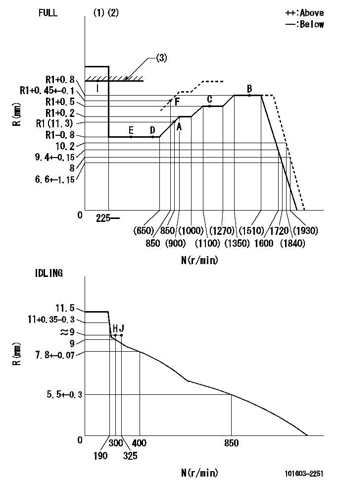
Injection quantity adjustment
Adjusting point
-
Rack position
11.3
Pump speed
r/min
850
850
850
Average injection quantity
mm3/st.
93
91
95
Max. variation between cylinders
%
0
-3.5
3.5
Basic
*
Fixing the rack
*
Standard for adjustment of the maximum variation between cylinders
*
Injection quantity adjustment_02
Adjusting point
Z
Rack position
9+-0.5
Pump speed
r/min
265
265
265
Each cylinder's injection qty
mm3/st.
15
14
16
Fixing the rack
*
Standard for adjustment of the maximum variation between cylinders
*
Injection quantity adjustment_03
Adjusting point
A
Rack position
R1(11.3)
Pump speed
r/min
850
850
850
Average injection quantity
mm3/st.
93
92
94
Basic
*
Fixing the lever
*
Injection quantity adjustment_04
Adjusting point
B
Rack position
R1+0.8
Pump speed
r/min
1450
1450
1450
Average injection quantity
mm3/st.
96
92
100
Fixing the lever
*
Injection quantity adjustment_05
Adjusting point
D
Rack position
R1-0.8
Pump speed
r/min
580
580
580
Average injection quantity
mm3/st.
74.5
70.5
78.5
Fixing the lever
*
Injection quantity adjustment_06
Adjusting point
I
Rack position
-
Pump speed
r/min
100
100
100
Average injection quantity
mm3/st.
140
140
150
Fixing the lever
*
Rack limit
*
Timer adjustment
Pump speed
r/min
1100+50
Advance angle
deg.
0
0
0
Remarks
Start
Start
Timer adjustment_02
Pump speed
r/min
1450-50
Advance angle
deg.
3.5
3.2
3.8
Remarks
Finish
Finish
Test data Ex:
Governor adjustment
N:Pump speed
R:Rack position (mm)
(1)Torque cam stamping: T1
(2)Tolerance for racks not indicated: +-0.05mm.
(3)RACK LIMIT
----------
T1=L26
----------
----------
T1=L26
----------
Speed control lever angle
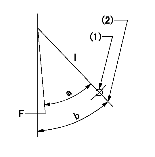
F:Full speed
I:Idle
(1)Use the pin at R = aa
(2)Stopper bolt set position 'H'
----------
aa=57mm
----------
a=38deg+-3deg b=44deg+-5deg
----------
aa=57mm
----------
a=38deg+-3deg b=44deg+-5deg
Stop lever angle
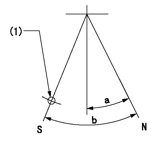
N:Pump normal
S:Stop the pump.
(1)Use the hole at R = aa
----------
aa=35mm
----------
a=14.5deg+-5deg b=40deg+-5deg
----------
aa=35mm
----------
a=14.5deg+-5deg b=40deg+-5deg
0000001501 TAMPER PROOF
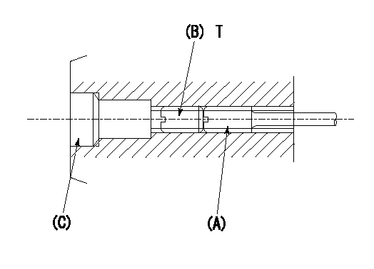
1. Method for setting tamperproof proofing
(1)Perform after governor adjustment (torque cam phase adjustment).
(2)Increase the full rack position to Ra using the load lever.
(3)Push in screw (A) to Rb.
(4)Temporarily caulk using the tip of a screwdriver
(5)Confirm that the rack at that time is at Rb .
(6)Lock using setscrew (B). (Tightening torque = T)
(7)Pressfit (C) after applying adhesive.
(8)Readjust the full rack using the load lever.
----------
Ra=R1+0.45+-0.1mm Rb=R1+0.45+-0.1mm
----------
T=3.4~4.9N-m(0.35~0.5Kgf-m)
----------
Ra=R1+0.45+-0.1mm Rb=R1+0.45+-0.1mm
----------
T=3.4~4.9N-m(0.35~0.5Kgf-m)
Timing setting

(1)Pump vertical direction
(2)Coupling's key groove position at No 1 cylinder's beginning of injection
(3)-
(4)-
----------
----------
a=(50deg)
----------
----------
a=(50deg)
Information:
Lubrication System
Oil Lubrication Schematic
Oil Pump
(1) Strainer. (2) Oil Pump relief valve. (3) Oil pump. (4) Idler gear. (5) Crankshaft gear.The lubrication system is the pressure type and the flow of oil goes from the oil pan through strainer (1) into oil pump (3). Oil pump (3) is driven by crankshaft gear (5) through idler gear (4). The oil pump is connected to the front main bearing cap. Relief valve (2) which is spring loaded controls the maximum oil pressure. An oil pressure sending unit is connected to the main oil gallery.Oil under pressure goes from the oil pump through the relief valve and filter. On the T4.236 Engines, oil passes first through the oil cooler. The oil cooler is cooled by water from the cooling system. On engines that have a center mounted balancer unit, the oil pump and relief valve are integral with the balancer unit.Oil flows through the filter to the main oil gallery which is a drilled passage the length of the crankcase. A pipe from the filter head feeds oil to the turbocharger bearings on T4.236 Engines.From the gallery the oil flows through drilled passages to the main bearing bores and then through the crankshaft passages to the big end (rod) bearings. T4.236 Engine oil also flows from the main oil gallery to the piston cooling jets which have integral relief valves. The piston cooling jets feed oil to the underside of the pistons, where the oil circulates, taking heat from the combustion area. The cooling jets start operation at approximately 205 kPa (30 psi).
Timing Gears
(6) Idler gear. (7) Idler gear retainer plate.The crankshaft bearings are lubricated from numbers 1, 3 and 5 main bearings. The camshaft center bearing supplies a controlled amount of oil to the rocker shaft assembly. Oil from the rocker shaft drains through a bleed hole in each rocker lever to lubricate the valves and valve guides.Oil also goes from the gallery through the rear of idler gear (6) hub, then through passages to lubricate the idler gear bearing and gear retainer plate (7).Pistons, cylinder liners, connecting rod small end bushings, cam lobes and tappets (valve lifters) are splash and oil mist lubricated.Balancer Unit
Center Mounted Balancer Unit Components
(1) Idler gear hub. (2) Idler gear bearing. (3) Idler gear. (4) Idler gear thrust washer. (5) Balance weight bushings. (6) Balance weights. (7) Oil transfer cover plate. (8) Balancer frame. (9) Oil pump relief valve assembly. (10) Balance weights drive gear. (11) Gear shaft drive bearings. (12) Gear shaft drive. (13) Oil pump. (14) Oil suction pipe.Engines that are mounted stationary (rigid) have a balancer unit that is mounted to the block bottom face in the center of the engine. The balancer unit is timed to and driven by the crankshaft through a gear on the crankshaft and idler gear (3). The rotation of timed balance weights (10) counteracts the movement of the pistons and connecting rods of the engine.Oil pump (13) is part of and is driven by the balancer unit
Have questions with 101603-2251?
Group cross 101603-2251 ZEXEL
Hino
Hino
Hino
101603-2251
INJECTION-PUMP ASSEMBLY