Information injection-pump assembly
ZEXEL
101603-2250
1016032250
HINO
220009060A
220009060a
Rating:
Cross reference number
ZEXEL
101603-2250
1016032250
HINO
220009060A
220009060a
Zexel num
Bosch num
Firm num
Name
Calibration Data:
Adjustment conditions
Test oil
1404 Test oil ISO4113 or {SAEJ967d}
1404 Test oil ISO4113 or {SAEJ967d}
Test oil temperature
degC
40
40
45
Nozzle and nozzle holder
105780-8260
Bosch type code
9 430 610 133
Nozzle
105780-0120
Bosch type code
1 688 901 990
Nozzle holder
105780-2190
Opening pressure
MPa
18
Opening pressure
kgf/cm2
184
Injection pipe
Outer diameter - inner diameter - length (mm) mm 6-2-600
Outer diameter - inner diameter - length (mm) mm 6-2-600
Overflow valve
131425-0620
Overflow valve opening pressure
kPa
255
221
289
Overflow valve opening pressure
kgf/cm2
2.6
2.25
2.95
Tester oil delivery pressure
kPa
255
255
255
Tester oil delivery pressure
kgf/cm2
2.6
2.6
2.6
Direction of rotation (viewed from drive side)
Right R
Right R
Injection timing adjustment
Direction of rotation (viewed from drive side)
Right R
Right R
Injection order
1-4-2-6-
3-5
Pre-stroke
mm
4
3.97
4.03
Beginning of injection position
Drive side NO.1
Drive side NO.1
Difference between angles 1
Cal 1-4 deg. 60 59.75 60.25
Cal 1-4 deg. 60 59.75 60.25
Difference between angles 2
Cyl.1-2 deg. 120 119.75 120.25
Cyl.1-2 deg. 120 119.75 120.25
Difference between angles 3
Cal 1-6 deg. 180 179.75 180.25
Cal 1-6 deg. 180 179.75 180.25
Difference between angles 4
Cal 1-3 deg. 240 239.75 240.25
Cal 1-3 deg. 240 239.75 240.25
Difference between angles 5
Cal 1-5 deg. 300 299.75 300.25
Cal 1-5 deg. 300 299.75 300.25
Injection quantity adjustment
Adjusting point
-
Rack position
11.3
Pump speed
r/min
850
850
850
Average injection quantity
mm3/st.
93
91
95
Max. variation between cylinders
%
0
-3.5
3.5
Basic
*
Fixing the rack
*
Standard for adjustment of the maximum variation between cylinders
*
Injection quantity adjustment_02
Adjusting point
Z
Rack position
9+-0.5
Pump speed
r/min
265
265
265
Each cylinder's injection qty
mm3/st.
15
14
16
Fixing the rack
*
Standard for adjustment of the maximum variation between cylinders
*
Injection quantity adjustment_03
Adjusting point
A
Rack position
R1(11.3)
Pump speed
r/min
850
850
850
Average injection quantity
mm3/st.
93
92
94
Basic
*
Fixing the lever
*
Injection quantity adjustment_04
Adjusting point
B
Rack position
R1+0.8
Pump speed
r/min
1450
1450
1450
Average injection quantity
mm3/st.
96
92
100
Fixing the lever
*
Injection quantity adjustment_05
Adjusting point
D
Rack position
R1-0.8
Pump speed
r/min
580
580
580
Average injection quantity
mm3/st.
74.5
70.5
78.5
Fixing the lever
*
Injection quantity adjustment_06
Adjusting point
I
Rack position
-
Pump speed
r/min
100
100
100
Average injection quantity
mm3/st.
140
140
150
Fixing the lever
*
Rack limit
*
Timer adjustment
Pump speed
r/min
1100+50
Advance angle
deg.
0
0
0
Remarks
Start
Start
Timer adjustment_02
Pump speed
r/min
1450-50
Advance angle
deg.
3.5
3.2
3.8
Remarks
Finish
Finish
Test data Ex:
Governor adjustment
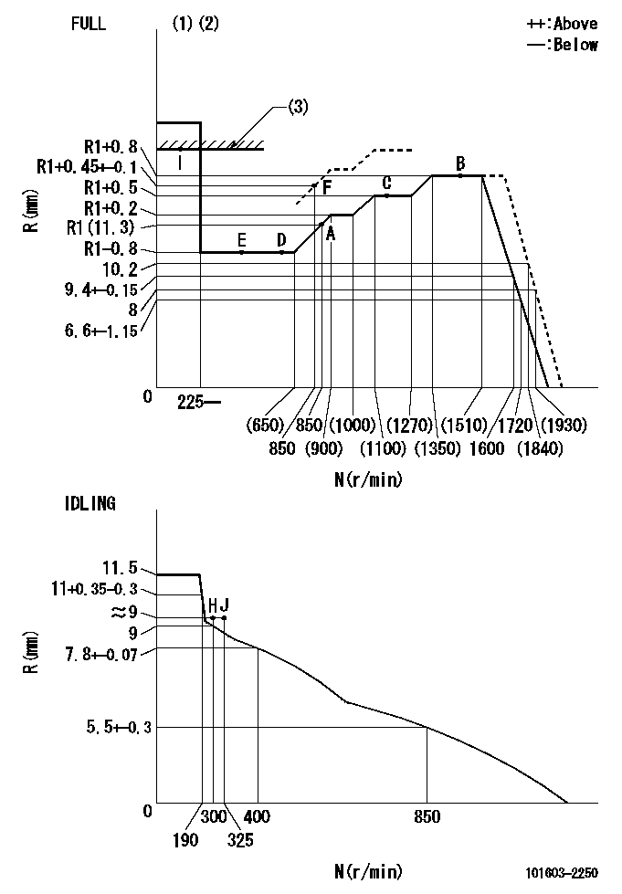
N:Pump speed
R:Rack position (mm)
(1)Torque cam stamping: T1
(2)Tolerance for racks not indicated: +-0.05mm.
(3)RACK LIMIT
----------
T1=L26
----------
----------
T1=L26
----------
Speed control lever angle
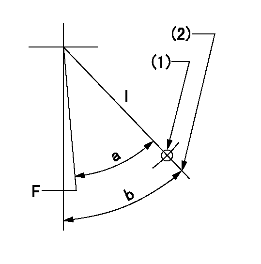
F:Full speed
I:Idle
(1)Use the pin at R = aa
(2)Stopper bolt set position 'H'
----------
aa=57mm
----------
a=38deg+-3deg b=44deg+-5deg
----------
aa=57mm
----------
a=38deg+-3deg b=44deg+-5deg
Stop lever angle
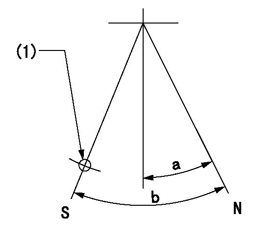
N:Pump normal
S:Stop the pump.
(1)Use the hole at R = aa
----------
aa=35mm
----------
a=14.5deg+-5deg b=40deg+-5deg
----------
aa=35mm
----------
a=14.5deg+-5deg b=40deg+-5deg
0000001501 TAMPER PROOF
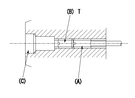
1. Method for setting tamperproof proofing
(1)Perform after governor adjustment (torque cam phase adjustment).
(2)Increase the full rack position to Ra using the load lever.
(3)Push in screw (A) to Rb.
(4)Temporarily caulk using the tip of a screwdriver
(5)Confirm that the rack at that time is at Rb .
(6)Lock using setscrew (B). (Tightening torque = T)
(7)Pressfit (C) after applying adhesive.
(8)Readjust the full rack using the load lever.
----------
Ra=R1+0.45+-0.1mm Rb=R1+0.45+-0.1mm
----------
T=3.4~4.9N-m(0.35~0.5Kgf-m)
----------
Ra=R1+0.45+-0.1mm Rb=R1+0.45+-0.1mm
----------
T=3.4~4.9N-m(0.35~0.5Kgf-m)
Timing setting

(1)Pump vertical direction
(2)Coupling's key groove position at No 1 cylinder's beginning of injection
(3)-
(4)-
----------
----------
a=(50deg)
----------
----------
a=(50deg)
Information:
(1) Balancer unit idler gear: Inside diameter of gear bore ... 47.635 to 47.650 mm (1.8754 to 1.8760 in)Outside diameter of gear bearing ... 47.63 mm (1.875 in)Inside diameter of gear bearing ... 38.1 mm (1.50 in)Outside diameter of idler gear hub ... 38.090 to 38.100 mm (1.4996 to 1.5000 in)Idler gear end play ... 0.08 to 0.23 mm (.003 to .009 in)Torque for idler gear bolt ... 75 N m (55 lb ft)(2) Idler gear thrust washer: Thrust washer thickness ... 4.14 to 4.29 mm (.163 to .169 in)Outside diameter of thrust washer ... 59.00 mm (2.323 in)Inside diameter of thrust washer ... 19.99 mm (0.787 in)
Be sure thread lock does not get on gear shaft drive needle bearing or it can cause the needle bearing to fail.
(3) Put 9S3263 Thread Lock on balance weight drive gear splines and threads for nut (3). Torque for nut ... 85 N m (65 lb ft)Diameter of balance weight drive gear splines ... 16.51 to 16.54 mm (.650 to .651 in)
If the oil transfer cover plate arrow points to the wrong side of the engine, the engine will seize due to the lack of lubrication.
(4) Torque for end cover bolts ... 55 N m (40 lb ft)(5) Install oil transfer cover plate with arrow pointing to side of engine that oil filter is on. Torque for cover plate bolts ... 30 N m (24 lb ft)(6) Gear shaft drive: Diameter of drive shaft at front bearing ... 28.55 to 28.58 mm (1.124 to 1.125 in)Diameter of drive shaft at rear bearing ... 23.77 to 23.80 mm (.936 to .937 in)Diameter of oil pump drive splines ... 28.55 to 28.58 mm (1.124 to 1.125 in)Diameter of front bearing bore ... 34.90 to 34.93 mm (1.374 to 1.375 in)Outside diameter of front bearing ... 34.920 mm (1.3748 in)Inside diameter of front bearing ... 28.58 mm (1.125 in)Diameter of rear bearing bore ... 45.72 to 45.85 mm (1.800 to 1.805 in)Outside diameter of rear bearing ... 30.00 mm (1.181 in)Inside diameter of rear bearing ... 23.80 mm (.937 in)End play of drive shaft ... 0.170 to 0.348 mm (.0067 to .0137 in)(7) Drive shaft front bearing dimension below front face of frame ... 2.49 to 3.00 mm (.098 to .118 in)(8) Length of drive shaft between rear bearing and front face of shaft ... 130.20 to 131.17 mm (5.126 to 5.164 in)(9) Drive shaft rear bearing dimension below machined surface ... 0.201 to 2.997 mm (.0079 to .1180 in) (10) Balance weights: Diameter of balance frame and end bushing bores ... 42.06 to 42.09 mm (1.656 to 1.657 in)Outside diameter of balance frame and end frame bushings ... 42.2 mm (1.66 in)Inside diameter of balance frame and end frame bushings ... 38.13 to 38.18 mm (1.501 to 1.503 in)Shaft diameter of balance weights ... 38.05 to 38.07 mm (1.498 to 1.499 in)Clearance between balance weight shafts and bushings ... 0.064