Information injection-pump assembly
BOSCH
9 400 615 044
9400615044
ZEXEL
101603-2221
1016032221
HINO
220204551A
220204551a
Rating:
Include in #1:
101603-7472
as _
Cross reference number
BOSCH
9 400 615 044
9400615044
ZEXEL
101603-2221
1016032221
HINO
220204551A
220204551a
Zexel num
Bosch num
Firm num
Name
101603-2221
9 400 615 044
220204551A HINO
INJECTION-PUMP ASSEMBLY
H07C-T K
H07C-T K
Calibration Data:
Adjustment conditions
Test oil
1404 Test oil ISO4113 or {SAEJ967d}
1404 Test oil ISO4113 or {SAEJ967d}
Test oil temperature
degC
40
40
45
Nozzle and nozzle holder
105780-8140
Bosch type code
EF8511/9A
Nozzle
105780-0000
Bosch type code
DN12SD12T
Nozzle holder
105780-2080
Bosch type code
EF8511/9
Opening pressure
MPa
17.2
Opening pressure
kgf/cm2
175
Injection pipe
Outer diameter - inner diameter - length (mm) mm 6-2-600
Outer diameter - inner diameter - length (mm) mm 6-2-600
Overflow valve
134424-0920
Overflow valve opening pressure
kPa
162
147
177
Overflow valve opening pressure
kgf/cm2
1.65
1.5
1.8
Tester oil delivery pressure
kPa
157
157
157
Tester oil delivery pressure
kgf/cm2
1.6
1.6
1.6
Direction of rotation (viewed from drive side)
Right R
Right R
Injection timing adjustment
Direction of rotation (viewed from drive side)
Right R
Right R
Injection order
1-4-2-6-
3-5
Pre-stroke
mm
4.8
4.77
4.83
Beginning of injection position
Drive side NO.1
Drive side NO.1
Difference between angles 1
Cal 1-4 deg. 60 59.75 60.25
Cal 1-4 deg. 60 59.75 60.25
Difference between angles 2
Cyl.1-2 deg. 120 119.75 120.25
Cyl.1-2 deg. 120 119.75 120.25
Difference between angles 3
Cal 1-6 deg. 180 179.75 180.25
Cal 1-6 deg. 180 179.75 180.25
Difference between angles 4
Cal 1-3 deg. 240 239.75 240.25
Cal 1-3 deg. 240 239.75 240.25
Difference between angles 5
Cal 1-5 deg. 300 299.75 300.25
Cal 1-5 deg. 300 299.75 300.25
Injection quantity adjustment
Adjusting point
A
Rack position
9.7
Pump speed
r/min
1050
1050
1050
Average injection quantity
mm3/st.
99.5
98
101
Max. variation between cylinders
%
0
-3.5
3.5
Basic
*
Fixing the lever
*
Boost pressure
kPa
27.3
27.3
Boost pressure
mmHg
205
205
Injection quantity adjustment_02
Adjusting point
-
Rack position
6.6+-0.5
Pump speed
r/min
410
410
410
Average injection quantity
mm3/st.
10
9
11
Max. variation between cylinders
%
0
-10
10
Fixing the rack
*
Boost pressure
kPa
0
0
0
Boost pressure
mmHg
0
0
0
Remarks
Adjust only variation between cylinders; adjust governor according to governor specifications.
Adjust only variation between cylinders; adjust governor according to governor specifications.
Injection quantity adjustment_03
Adjusting point
D
Rack position
-
Pump speed
r/min
100
100
100
Average injection quantity
mm3/st.
130
130
140
Fixing the lever
*
Boost pressure
kPa
0
0
0
Boost pressure
mmHg
0
0
0
Rack limit
*
Boost compensator adjustment
Pump speed
r/min
800
800
800
Rack position
R1-0.4
Boost pressure
kPa
12
12
13.3
Boost pressure
mmHg
90
90
100
Boost compensator adjustment_02
Pump speed
r/min
800
800
800
Rack position
R1(9.7)
Boost pressure
kPa
16.7
12.7
20.7
Boost pressure
mmHg
125
95
155
Timer adjustment
Pump speed
r/min
900--
Advance angle
deg.
0
0
0
Remarks
Start
Start
Timer adjustment_02
Pump speed
r/min
850
Advance angle
deg.
0.3
Timer adjustment_03
Pump speed
r/min
1050
Advance angle
deg.
1.5
1.2
1.8
Remarks
Finish
Finish
Test data Ex:
Governor adjustment
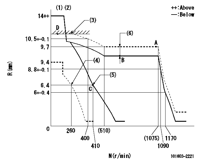
N:Pump speed
R:Rack position (mm)
(1)Target notch: K
(2)Tolerance for racks not indicated: +-0.05mm.
(3)RACK LIMIT
(4)Set idle sub-spring
(5)Main spring setting
(6)Boost compensator stroke: BCL
----------
K=13 BCL=0.4+-0.1mm
----------
----------
K=13 BCL=0.4+-0.1mm
----------
Speed control lever angle

F:Full speed
I:Idle
(1)Stopper bolt setting
----------
----------
a=6deg+-5deg b=20deg+-5deg
----------
----------
a=6deg+-5deg b=20deg+-5deg
Stop lever angle

N:Pump normal
S:Stop the pump.
(1)Pump speed aa and rack position bb (to be sealed at delivery)
(2)Normal
----------
aa=0r/min bb=1-0.5mm
----------
a=21deg+-5deg b=(55deg)
----------
aa=0r/min bb=1-0.5mm
----------
a=21deg+-5deg b=(55deg)
Timing setting

(1)Pump vertical direction
(2)Coupling's key groove position at No 1 cylinder's beginning of injection
(3)-
(4)-
----------
----------
a=(50deg)
----------
----------
a=(50deg)
Information:
3306 New Scroll Fuel System (NSFS)
See the service manual for your engine for other adjusting procedures.
Rack Adjustment For Engines With NSFS
Rear Of Governor
1. Opening for variable power actuator.1. Remove the variable power actuator from the rear of the governor.2. Adjust the high power fuel setting using the standard fuel system setting procedure in the service manual.For the correct fuel setting specifications, see the Engine Information Plate or the FUEL SETTING AND RELATED INFORMATION FICHE.
6V7941 Compressor Assembly
Governor And Compressor
2. 6V7941 Compressor Assembly.3. Remove the 6V7941 Compressor Assembly (2) and replace the plug in the rear of the governor housing.
Variable Power Actuator
3. Rod. 4. Washered nut. 5. Jam nut. 6. Dust cover.4. Remove the dust cover (6) from the variable power actuator. Loosen the jam nut (5) on the rod (3). Tighten the washered nut (4) to put rod (3) in the fully retracted position.
Governor And Actuator
3. Rod. 4. Washered nut. 5. Jam nut. 7. Actuator.5. Install actuator (7) in governor housing opening (1).6. Move the governor control to the high idle position and hold or fasten the governor control in this position.7. Extend the actuator rod (3), by loosening the washered nut (4), to achieve a minimum dial indicator reading of 2.0 mm (.08 in.) less than the desired low power fuel setting.EXAMPLE: If the low power rack adjustment specification is 3.0 mm (.12 in.), the actuator rod (3) must be adjusted to obtain a dial indicator reading of 1.0 mm (.04 in.).8. Tighten the washered nut (4), to retract the actuator rod (3) and increase the dial indicator reading to the specified low power fuel setting.For the correct fuel setting specifications, see the Engine Information Plate or the FUEL SETTING AND RELATED INFORMATION FICHE.9. If the low power fuel setting is exceeded, repeat steps 7 and 8.10. Tighten the jam nut (5) on the actuator rod (3) and install the dust cover (6).3304 SMFS Air Only Actuator
See the service manual for your engine for other testing and adjusting procedures.
Rack Adjustment For Engines With Sleeve Metering Fuel System (SMFS)
1. Remove the variable power actuator (1) from the rear of the governor (2).2. Use the fuel setting procedure in the service manual and adjust the high power fuel setting screw.For the correct fuel setting specifications, see the Engine Information Plate or the FUEL SETTING AND RELATED INFORMATION FICHE.3. Install the variable power actuator (1).4. Remove the back cover (6) from the actuator (1) to expose the adjustment pin (5).5. Move the governor control shaft to the high idle position.6. Turn the adjustment pin (5) clockwise to adjust the variable power control rod (8) to the fully EXTENDED position.7. To adjust the low power setting, turn the adjustment pin (5) counterclockwise to retract rod (8). Retract the rod (8) until the rack setting is decreased to the specified setting.For the correct fuel setting specifications, see the Engine Information Plate or the FUEL SETTING AND RELATED INFORMATION FICHE.8. Replace cover (6) on the variable power actuator (6).
Governor And Variable Power Actuator
1. Variable
Have questions with 101603-2221?
Group cross 101603-2221 ZEXEL
Hino
Hino
101603-2221
9 400 615 044
220204551A
INJECTION-PUMP ASSEMBLY
H07C-T
H07C-T