Information injection-pump assembly
BOSCH
9 400 615 041
9400615041
ZEXEL
101603-2151
1016032151
HINO
220008590B
220008590b
Rating:
Service parts 101603-2151 INJECTION-PUMP ASSEMBLY:
1.
_
6.
COUPLING PLATE
7.
COUPLING PLATE
8.
_
9.
_
11.
Nozzle and Holder
12.
Open Pre:MPa(Kqf/cm2)
21.6{220}
15.
NOZZLE SET
Cross reference number
BOSCH
9 400 615 041
9400615041
ZEXEL
101603-2151
1016032151
HINO
220008590B
220008590b
Zexel num
Bosch num
Firm num
Name
101603-2151
9 400 615 041
220008590B HINO
INJECTION-PUMP ASSEMBLY
W06E K 14BE INJECTION PUMP ASSY PE6A PE
W06E K 14BE INJECTION PUMP ASSY PE6A PE
Calibration Data:
Adjustment conditions
Test oil
1404 Test oil ISO4113 or {SAEJ967d}
1404 Test oil ISO4113 or {SAEJ967d}
Test oil temperature
degC
40
40
45
Nozzle and nozzle holder
105780-8140
Bosch type code
EF8511/9A
Nozzle
105780-0000
Bosch type code
DN12SD12T
Nozzle holder
105780-2080
Bosch type code
EF8511/9
Opening pressure
MPa
17.2
Opening pressure
kgf/cm2
175
Injection pipe
Outer diameter - inner diameter - length (mm) mm 6-2-600
Outer diameter - inner diameter - length (mm) mm 6-2-600
Overflow valve
131424-5720
Overflow valve opening pressure
kPa
255
221
289
Overflow valve opening pressure
kgf/cm2
2.6
2.25
2.95
Tester oil delivery pressure
kPa
157
157
157
Tester oil delivery pressure
kgf/cm2
1.6
1.6
1.6
Direction of rotation (viewed from drive side)
Right R
Right R
Injection timing adjustment
Direction of rotation (viewed from drive side)
Right R
Right R
Injection order
1-4-2-6-
3-5
Pre-stroke
mm
3.1
3.07
3.13
Beginning of injection position
Drive side NO.1
Drive side NO.1
Difference between angles 1
Cal 1-4 deg. 60 59.75 60.25
Cal 1-4 deg. 60 59.75 60.25
Difference between angles 2
Cyl.1-2 deg. 120 119.75 120.25
Cyl.1-2 deg. 120 119.75 120.25
Difference between angles 3
Cal 1-6 deg. 180 179.75 180.25
Cal 1-6 deg. 180 179.75 180.25
Difference between angles 4
Cal 1-3 deg. 240 239.75 240.25
Cal 1-3 deg. 240 239.75 240.25
Difference between angles 5
Cal 1-5 deg. 300 299.75 300.25
Cal 1-5 deg. 300 299.75 300.25
Injection quantity adjustment
Adjusting point
-
Rack position
9.5
Pump speed
r/min
900
900
900
Average injection quantity
mm3/st.
60.2
58.2
62.2
Max. variation between cylinders
%
0
-3.5
3.5
Basic
*
Fixing the rack
*
Standard for adjustment of the maximum variation between cylinders
*
Injection quantity adjustment_02
Adjusting point
H
Rack position
8+-0.5
Pump speed
r/min
250
250
250
Average injection quantity
mm3/st.
6.8
5.3
8.3
Max. variation between cylinders
%
0
-10
10
Fixing the rack
*
Standard for adjustment of the maximum variation between cylinders
*
Injection quantity adjustment_03
Adjusting point
A
Rack position
R1(9.5)
Pump speed
r/min
900
900
900
Average injection quantity
mm3/st.
60.2
59.2
61.2
Basic
*
Fixing the lever
*
Injection quantity adjustment_04
Adjusting point
B
Rack position
R1+0.1
Pump speed
r/min
1500
1500
1500
Average injection quantity
mm3/st.
67.3
63.3
71.3
Fixing the lever
*
Injection quantity adjustment_05
Adjusting point
C
Rack position
R1-0.45
Pump speed
r/min
600
600
600
Average injection quantity
mm3/st.
37.9
33.9
41.9
Fixing the lever
*
Injection quantity adjustment_06
Adjusting point
D
Rack position
R1+0.15
Pump speed
r/min
1200
1200
1200
Average injection quantity
mm3/st.
67.8
63.8
71.8
Fixing the lever
*
Injection quantity adjustment_07
Adjusting point
E
Rack position
R1(9.5)
Pump speed
r/min
400
400
400
Average injection quantity
mm3/st.
32.9
28.9
36.9
Fixing the lever
*
Injection quantity adjustment_08
Adjusting point
I
Rack position
13.9+-0.
5
Pump speed
r/min
100
100
100
Average injection quantity
mm3/st.
99
99
109
Fixing the lever
*
Rack limit
*
Injection quantity adjustment_09
Adjusting point
F
Rack position
R2(10)
Pump speed
r/min
1500
1500
1500
Average injection quantity
mm3/st.
72.765
67.765
77.765
Fixing the lever
*
Remarks
Set tamper proofing.
Set tamper proofing.
Timer adjustment
Pump speed
r/min
1000+50
Advance angle
deg.
0
0
0
Remarks
Start
Start
Timer adjustment_02
Pump speed
r/min
1500
Advance angle
deg.
3.5
3.2
3.8
Remarks
Finish
Finish
Test data Ex:
Governor adjustment
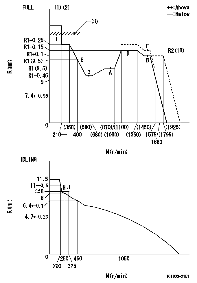
N:Pump speed
R:Rack position (mm)
(1)Torque cam stamping: T1
(2)Tolerance for racks not indicated: +-0.05mm.
(3)RACK LIMIT
----------
T1=C10
----------
----------
T1=C10
----------
Speed control lever angle

F:Full speed
I:Idle
(1)Stopper bolt set position 'H'
----------
----------
a=32deg+-3deg b=34deg+-5deg
----------
----------
a=32deg+-3deg b=34deg+-5deg
Stop lever angle
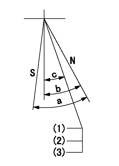
N:Pump normal
S:Stop the pump.
(1)Stopper bolt setting
(2)(Apply red paint after setting.)
(3)Engine normal
----------
----------
a=40deg+-5deg b=40deg+-5deg c=35deg+-2deg
----------
----------
a=40deg+-5deg b=40deg+-5deg c=35deg+-2deg
0000001501 ACS

(A) Set screw
(B) Push rod 1
(C) Push rod 2
(D) Cover
1. Aneroid compensator unit adjustment
(1)Select the push rod 2 to obtain L2.
(2)Screw in (A) to obtain L1.
2. Adjustment when mounting the governor.
(1)Set the speed of the pump to N1 r/min and fix the control lever at the full set position.
(2)Screw in the aneroid compensator to obtain the performance shown in the graph above.
(3)As there is hysterisis, measure when the absolute pressure drops.
(4)Hysterisis must not exceed rack position = h1.
----------
N1=1500r/min L1=(1.5)mm L2=7+-0.5mm h1=-
----------
Ra=R1+0.1mm Rb=R1-1.65mm Pa=(94.6)+-2.7kPa((710)+-20mmHg) Pb=61.6+-0.7kPa(462+-5mmHg) Q1=(67.3)+-2cm3/1000st Q2=-
----------
N1=1500r/min L1=(1.5)mm L2=7+-0.5mm h1=-
----------
Ra=R1+0.1mm Rb=R1-1.65mm Pa=(94.6)+-2.7kPa((710)+-20mmHg) Pb=61.6+-0.7kPa(462+-5mmHg) Q1=(67.3)+-2cm3/1000st Q2=-
0000001601 TAMPER PROOF
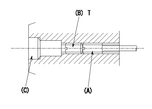
1. Method for setting tamperproof proofing
(1)Perform after governor adjustment (torque cam phase adjustment).
(2)Increase the full rack position to Ra using the load lever.
(3)Push in screw (A) to Rb.
(4)Temporarily caulk using the tip of a screwdriver
(5)Confirm that the rack at that time is at Rb .
(6)Lock using setscrew (B). (Tightening torque = T)
(7)Pressfit (C) after applying adhesive.
(8)Readjust the full rack using the load lever.
----------
Ra=R2(10)mm Rb=R2(10)mm
----------
T=4.9~7N-m(0.5~0.7Kgf-m)
----------
Ra=R2(10)mm Rb=R2(10)mm
----------
T=4.9~7N-m(0.5~0.7Kgf-m)
Timing setting

(1)Pump vertical direction
(2)Position of gear's standard threaded hole at No 1 cylinder's beginning of injection
(3)-
(4)-
----------
----------
a=(70deg)
----------
----------
a=(70deg)
Information:
Illustration 16 g00628694
(9) Fuel injector clamp. (10) Bolt. (11) O-ring seal.
Place the clamp (9) in the proper position. Temporarily place the jumper tube in position in order to ensure alignment of the bolt holes. Adjust the orientation of the injector until the alignment is satisfactory. Torque the bolt (10) to the following torque. Remove the jumper tube.Torque for bolt ... 47 9 N m (35 7 lb ft)
Illustration 17 g00628691
(12) O-ring seals in the injector jumper tube. (13) O-ring seals in the base of the rocker arm.
Replace the used O-ring seal (11), and the O-ring seals (12) and (13) in the jumper tube and in the rocker arm.
Illustration 18 g00628693
(14) Jumper tube. (15) Bolts. (16) Adapter. (17) Socket head screws.
Place the jumper tube (14) and the adapter (16) into position.
If the adapter was previously installed on the injector, loosen the socket head screws. Failure to loosen the socket head screws before continuing with Step 8 can result in injector failure.
Install the socket head screws (17) and the four bolts (15) finger tight.Note: The mating surfaces should be brought into complete contact and into alignment before the final torque procedure is started.
Failure to follow any of the procedures in this instruction may result in injector damage or malfunction, and possible major engine damage.
Torque Procedure
Illustration 19 g00338156
(1) Socket head screws.
Illustration 20 g00338157
(2) Two horizontal bolts. (3) Two vertical bolts.
Tighten the socket head screws (1), the two horizontal bolts (2), and the two vertical bolts (3) finger tight.
Tighten the socket head screws (1) to an initial torque of 1 .2 N m (9 2 lb in).
Tighten the horizontal bolts (2) to an initial torque of 5 3 N m (44 27 lb in).
Tighten the vertical bolts (3) to an initial torque of 5 3 N m (44 27 lb in).
Tighten the socket head screws (1) to a final torque of 12 3 N m (9 2 lb ft).
Tighten the horizontal bolts (2) to a final torque of 47 9 N m (35 7 lb ft).
Tighten the vertical bolts (3) to a final torque of 47 9 N m (35 7 lb ft).
Repeat Step 1 through Step 7 for the remainder of the injectors.
Check the fuel system for leaks by cranking the engine with the disabled injection. Then check the hydraulic pressure. Compare the pressure to the desired pressure.Cranking Without Injecting
Cranking the engine with the disabled injection may be performed by one of the following methods:
Disconnect the injector harness of the cylinders which have been reinstalled. Allow the engine to idle. Visually inspect the injector's components for high pressure oil leaks.
Activate the system "Crank Without Inject" if the option is available. On Track-Type Tractors, a "Crank Without Inject" plug can be assembled in the engine harness. On Off-Highway Trucks, the "Ground Level Shutdown" can be activated if the option is available.
When you are using the CAT ET or the ECAP, the injection may be disabled by interactive diagnostics. The engine can be left
Have questions with 101603-2151?
Group cross 101603-2151 ZEXEL
Hino
Hino
Hino
Hino
Hino
101603-2151
9 400 615 041
220008590B
INJECTION-PUMP ASSEMBLY
W06E
W06E