Information injection-pump assembly
BOSCH
9 400 615 039
9400615039
ZEXEL
101603-2092
1016032092
HINO
220204400A
220204400a
Rating:
Service parts 101603-2092 INJECTION-PUMP ASSEMBLY:
1.
_
7.
COUPLING PLATE
8.
_
9.
_
11.
Nozzle and Holder
236002710A
12.
Open Pre:MPa(Kqf/cm2)
17.7{180}
15.
NOZZLE SET
Cross reference number
BOSCH
9 400 615 039
9400615039
ZEXEL
101603-2092
1016032092
HINO
220204400A
220204400a
Zexel num
Bosch num
Firm num
Name
101603-2092
9 400 615 039
220204400A HINO
INJECTION-PUMP ASSEMBLY
H07C-T * K
H07C-T * K
Calibration Data:
Adjustment conditions
Test oil
1404 Test oil ISO4113 or {SAEJ967d}
1404 Test oil ISO4113 or {SAEJ967d}
Test oil temperature
degC
40
40
45
Nozzle and nozzle holder
105780-8140
Bosch type code
EF8511/9A
Nozzle
105780-0000
Bosch type code
DN12SD12T
Nozzle holder
105780-2080
Bosch type code
EF8511/9
Opening pressure
MPa
17.2
Opening pressure
kgf/cm2
175
Injection pipe
Outer diameter - inner diameter - length (mm) mm 6-2-600
Outer diameter - inner diameter - length (mm) mm 6-2-600
Overflow valve
134424-0920
Overflow valve opening pressure
kPa
162
147
177
Overflow valve opening pressure
kgf/cm2
1.65
1.5
1.8
Tester oil delivery pressure
kPa
157
157
157
Tester oil delivery pressure
kgf/cm2
1.6
1.6
1.6
Direction of rotation (viewed from drive side)
Right R
Right R
Injection timing adjustment
Direction of rotation (viewed from drive side)
Right R
Right R
Injection order
1-4-2-6-
3-5
Pre-stroke
mm
4.8
4.77
4.83
Beginning of injection position
Drive side NO.1
Drive side NO.1
Difference between angles 1
Cal 1-4 deg. 60 59.75 60.25
Cal 1-4 deg. 60 59.75 60.25
Difference between angles 2
Cyl.1-2 deg. 120 119.75 120.25
Cyl.1-2 deg. 120 119.75 120.25
Difference between angles 3
Cal 1-6 deg. 180 179.75 180.25
Cal 1-6 deg. 180 179.75 180.25
Difference between angles 4
Cal 1-3 deg. 240 239.75 240.25
Cal 1-3 deg. 240 239.75 240.25
Difference between angles 5
Cal 1-5 deg. 300 299.75 300.25
Cal 1-5 deg. 300 299.75 300.25
Injection quantity adjustment
Adjusting point
A
Rack position
11.9
Pump speed
r/min
1000
1000
1000
Average injection quantity
mm3/st.
124.5
123
126
Max. variation between cylinders
%
0
-3.5
3.5
Basic
*
Fixing the lever
*
Boost pressure
kPa
33.3
33.3
Boost pressure
mmHg
250
250
Injection quantity adjustment_02
Adjusting point
-
Rack position
6.4+-0.5
Pump speed
r/min
450
450
450
Average injection quantity
mm3/st.
10
9
11
Max. variation between cylinders
%
0
-10
10
Fixing the rack
*
Boost pressure
kPa
0
0
0
Boost pressure
mmHg
0
0
0
Remarks
Adjust only variation between cylinders; adjust governor according to governor specifications.
Adjust only variation between cylinders; adjust governor according to governor specifications.
Injection quantity adjustment_03
Adjusting point
D
Rack position
-
Pump speed
r/min
100
100
100
Average injection quantity
mm3/st.
130
130
140
Fixing the lever
*
Boost pressure
kPa
0
0
0
Boost pressure
mmHg
0
0
0
Rack limit
*
Boost compensator adjustment
Pump speed
r/min
800
800
800
Rack position
R1-1.4
Boost pressure
kPa
4.7
2
7.4
Boost pressure
mmHg
35
15
55
Boost compensator adjustment_02
Pump speed
r/min
800
800
800
Rack position
R1(11.9)
Boost pressure
kPa
20
13.3
26.7
Boost pressure
mmHg
150
100
200
Timer adjustment
Pump speed
r/min
850--
Advance angle
deg.
0
0
0
Remarks
Start
Start
Timer adjustment_02
Pump speed
r/min
800
Advance angle
deg.
0.5
Timer adjustment_03
Pump speed
r/min
1050
Advance angle
deg.
2
1.5
2.5
Remarks
Finish
Finish
Test data Ex:
Governor adjustment
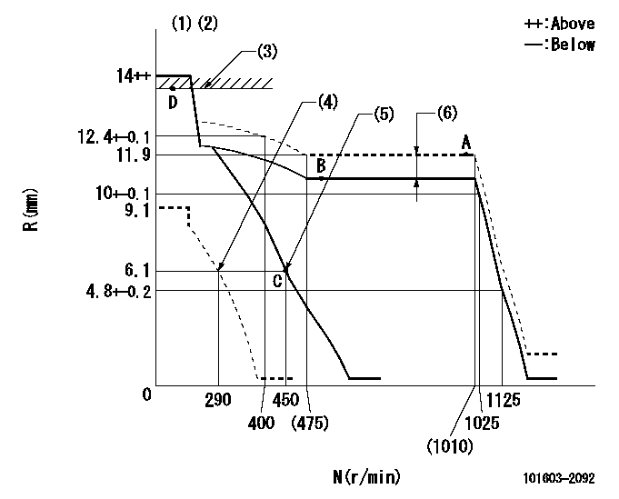
N:Pump speed
R:Rack position (mm)
(1)Target notch: K
(2)Tolerance for racks not indicated: +-0.05mm.
(3)RACK LIMIT
(4)Set idle sub-spring
(5)Main spring setting
(6)Boost compensator stroke: BCL
----------
K=14 BCL=1.4+-0.1mm
----------
----------
K=14 BCL=1.4+-0.1mm
----------
Speed control lever angle

F:Full speed
I:Idle
(1)Stopper bolt setting
----------
----------
a=10deg+-5deg b=25deg+-5deg
----------
----------
a=10deg+-5deg b=25deg+-5deg
Stop lever angle

N:Pump normal
S:Stop the pump.
(1)Pump speed aa and rack position bb (to be sealed at delivery)
(2)Normal
----------
aa=0r/min bb=1-0.5mm
----------
a=21deg+-5deg b=(55deg)
----------
aa=0r/min bb=1-0.5mm
----------
a=21deg+-5deg b=(55deg)
Timing setting

(1)Pump vertical direction
(2)Coupling's key groove position at No 1 cylinder's beginning of injection
(3)-
(4)-
----------
----------
a=(50deg)
----------
----------
a=(50deg)
Information:
Crankshaft Grinding Specifications
The dimensions and finish for grinding crankshafts are as follows:Diameter (A) for connecting rod bearing journals is;.010 in. (0.25 mm) Undersize ... 2.7396 .0006 in.(69.586 0.015 mm).020 in. (0.51 mm) Undersize ... 2.7296 .0006 in.(69.332 0.015 mm).050 in. (1.27 mm) Undersize ... 2.6996 .0006 in.(68.570 0.015 mm)Surface finish must be 10 micro inches (0.25 micrometers) or less.Radius (B) must be .100 .010 in. (2.54 0.25 mm).Surface finish must be 63 micro inches (1.6 micrometers) or less.The radius must blend smoothly with the newly machined journals.
DIMENSIONS FOR GRINDING
A. Diameter of connecting rod bearing journals. B. Radius on connecting rod bearing journals. C. Width to grind journals for the connecting rods. D. Diameter of main bearing journals. E. Radius on main bearing journals. F. Width to grind journals for the main bearings.Width (C) is 2.314 .003 in. (58.77 0.08 mm)Diameter (D) for main bearing journals is:.010 in. (0.25 mm) Undersize ... 3.4895 .0006 in.(88.633 0.015 mm).020 in. (0.51 mm) Undersize ... 3.4795 .0006 in.(88.379 0.015 mm).050 in. (1.27 mm) Undersize ... 3.4495 .0006 in.(87.617 0.015 mm)Surface finish must be 10 micro inches (0.25 micrometers) or less.Radius (E) must be .095 .010 in. (2.41 0.25 mm)Surface finish must be 63 micro inches (1.6 micrometers) or less.The radius must blend smoothly with the newly machined journals.Width (F) is 1.258 .002 in. (31.95 0.05 mm) for number 4 main bearing journal. Surface finish on the thrust faces of the number 4 main must be 18 micro inches (0.45 micrometers) or less.Width (F) is 1.268 + .020 - .010 in. (32.21 + 0.51 - 0.25 mm) for number 2, 3, and 5 main bearing journals.There is no width (F) for number 1 main bearing journal.When grinding a crankshaft, no material can be removed from the crankshaft webs or counterweights.Crankshaft Gear Removal
Remove the gear using an 8B7548 Push Puller, 8B7551 Bearing Pulling Attachment, 8B75621 Step Plate, and 8H684 Ratchet Box Wrench.
PULLING CRANKSHAFT GEARThe 1P820 Hydraulic Puller Group can also be used to pull gear from crankshaft. Tools required are 1P820 Hydraulic Puller Group, 8B7551 Bearing Pulling Attachment, 8B7549 Puller legs (two), 8B7561 Step Plate, 3H465 Plate (four), 1B4207 Nut (two), and 5P3100 Pump Group.
USING HYDRAULIC PULLERCrankshaft Gear Installation
1. Install the key in keyway of crankshaft. Remove all burrs from key and keyway inside of crankshaft gear.2. Heat gear to 500°F (260°C) maximum.3. Install gear on crankshaft with timing mark on gear facing front of crankshaft.Crankshaft Front Oil Seal Removal
Remove the crankshaft front pulley. Use the 1P3075 Puller Group to remove the crankshaft front oil seal.
REMOVING FRONT OIL SEAL (Typical Example)Remove Crankshaft Rear Seal And Wear Sleeve
Remove the crankshaft rear oil seal with the 1P3075 Puller Group.
REMOVING REAR OIL SEALInstall a 5P7338 Distorter Ring from the 5P7318 Wear Sleeve Distorter Group, in the rear seal bore.
REMOVING REAR WEAR SLEEVE (Typical Example)Install 5P7312 Distorter between distorter ring and wear sleeve. Turn the distorter until the
Have questions with 101603-2092?
Group cross 101603-2092 ZEXEL
Hino
Hino
Hino
101603-2092
9 400 615 039
220204400A
INJECTION-PUMP ASSEMBLY
H07C-T
H07C-T