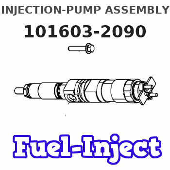
Information injection-pump assembly
ZEXEL
101603-2090
1016032090
Rating:
Service parts 101603-2090 INJECTION-PUMP ASSEMBLY:
1.
_
7.
COUPLING PLATE
8.
_
9.
_
11.
Nozzle and Holder
23600-2710A
12.
Open Pre:MPa(Kqf/cm2)
17.7{180}
15.
NOZZLE SET
Cross reference number
ZEXEL
101603-2090
1016032090
Zexel num
Bosch num
Firm num
Name
101603-2090
INJECTION-PUMP ASSEMBLY
14BD PE4AD PE
14BD PE4AD PE
Calibration Data:
Adjustment conditions
Test oil
1404 Test oil ISO4113 or {SAEJ967d}
1404 Test oil ISO4113 or {SAEJ967d}
Test oil temperature
degC
40
40
45
Nozzle and nozzle holder
105780-8140
Bosch type code
EF8511/9A
Nozzle
105780-0000
Bosch type code
DN12SD12T
Nozzle holder
105780-2080
Bosch type code
EF8511/9
Opening pressure
MPa
17.2
Opening pressure
kgf/cm2
175
Injection pipe
Outer diameter - inner diameter - length (mm) mm 6-2-600
Outer diameter - inner diameter - length (mm) mm 6-2-600
Overflow valve
134424-0920
Overflow valve opening pressure
kPa
162
147
177
Overflow valve opening pressure
kgf/cm2
1.65
1.5
1.8
Tester oil delivery pressure
kPa
157
157
157
Tester oil delivery pressure
kgf/cm2
1.6
1.6
1.6
Direction of rotation (viewed from drive side)
Right R
Right R
Injection timing adjustment
Direction of rotation (viewed from drive side)
Right R
Right R
Injection order
1-4-2-6-
3-5
Pre-stroke
mm
4.8
4.77
4.83
Beginning of injection position
Drive side NO.1
Drive side NO.1
Difference between angles 1
Cal 1-4 deg. 60 59.75 60.25
Cal 1-4 deg. 60 59.75 60.25
Difference between angles 2
Cyl.1-2 deg. 120 119.75 120.25
Cyl.1-2 deg. 120 119.75 120.25
Difference between angles 3
Cal 1-6 deg. 180 179.75 180.25
Cal 1-6 deg. 180 179.75 180.25
Difference between angles 4
Cal 1-3 deg. 240 239.75 240.25
Cal 1-3 deg. 240 239.75 240.25
Difference between angles 5
Cal 1-5 deg. 300 299.75 300.25
Cal 1-5 deg. 300 299.75 300.25
Injection quantity adjustment
Adjusting point
A
Rack position
11.9
Pump speed
r/min
1000
1000
1000
Average injection quantity
mm3/st.
124.5
123
126
Max. variation between cylinders
%
0
-3.5
3.5
Basic
*
Fixing the lever
*
Boost pressure
kPa
33.3
33.3
Boost pressure
mmHg
250
250
Injection quantity adjustment_02
Adjusting point
-
Rack position
6.4
Pump speed
r/min
450
450
450
Average injection quantity
mm3/st.
10
9
11
Max. variation between cylinders
%
0
-10
10
Fixing the rack
*
Boost pressure
kPa
0
0
0
Boost pressure
mmHg
0
0
0
Remarks
Adjust only variation between cylinders; adjust governor according to governor specifications.
Adjust only variation between cylinders; adjust governor according to governor specifications.
Injection quantity adjustment_03
Adjusting point
D
Rack position
-
Pump speed
r/min
100
100
100
Average injection quantity
mm3/st.
130
130
140
Fixing the lever
*
Boost pressure
kPa
0
0
0
Boost pressure
mmHg
0
0
0
Rack limit
*
Boost compensator adjustment
Pump speed
r/min
800
800
800
Rack position
R1-1.4
Boost pressure
kPa
4.7
2
7.4
Boost pressure
mmHg
35
15
55
Boost compensator adjustment_02
Pump speed
r/min
800
800
800
Rack position
R1(11.9)
Boost pressure
kPa
20
13.3
26.7
Boost pressure
mmHg
150
100
200
Timer adjustment
Pump speed
r/min
850--
Advance angle
deg.
0
0
0
Remarks
Start
Start
Timer adjustment_02
Pump speed
r/min
800
Advance angle
deg.
0.5
Timer adjustment_03
Pump speed
r/min
1050
Advance angle
deg.
2
1.5
2.5
Remarks
Finish
Finish
Test data Ex:
Governor adjustment
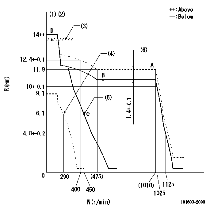
N:Pump speed
R:Rack position (mm)
(1)Target notch: K
(2)Tolerance for racks not indicated: +-0.05mm.
(3)RACK LIMIT
(4)Set idle sub-spring
(5)Main spring setting
(6)Boost compensator stroke
----------
K=14
----------
----------
K=14
----------
Speed control lever angle

F:Full speed
I:Idle
(1)Stopper bolt setting
----------
----------
a=10deg+-5deg b=25deg+-5deg
----------
----------
a=10deg+-5deg b=25deg+-5deg
Stop lever angle

N:Pump normal
S:Stop the pump.
(1)Speed = aa, rack position = bb (sealed at shipping)
----------
aa=0r/min bb=1-0.5mm
----------
a=21deg+-5deg b=(55deg)
----------
aa=0r/min bb=1-0.5mm
----------
a=21deg+-5deg b=(55deg)
Timing setting

(1)Pump vertical direction
(2)Coupling's key groove position at No 1 cylinder's beginning of injection
(3)-
(4)-
----------
----------
a=(50deg)
----------
----------
a=(50deg)
Information:
Cylinder Head And Valve Components
Check cylinder head for cracks before reconditioning.Flatness of the cylinder head should be within .006 in. (0.15 mm) total, and a maximum of .003 in. (0.08 mm) for any 6 in. (152.4 mm) span. A maximum stock removal of .010 in. (0.25 mm) is permissible when resurfacing the head.Always check the thickness of a cylinder head before resurfacing. The cylinder head may have been resurfaced before and would not have enough stock to be resurfaced again.To check the thickness of a cylinder head, measure through the fuel injection nozzle holes at each end of the cylinder head. For the correct thickness of the cylinder head, see the topic CYLINDER HEAD in the SPECIFICATIONS.The exhaust valve seats have replaceable inserts. To remove, use the 8S7170 Valve Seat Insert Puller Group.
REMOVING EXHAUST VALVE SEAT INSERTFreeze the exhaust valve seat inserts or use the 8S7170 Valve Seat Insert Puller Group to install inserts into head. Be sure bores are clean, free of burrs, and the insert has a good press fit into the bore.After inserts are installed, grind the seat face of the insert to be sure it is flat, has the correct angle, and is in alignment with the bore in the valve guide. For specifications, see VALVE GRINDING SPECIFICATIONS CHART. Replace exhaust valve seat inserts when valve seat width or valve head-to-cylinder head face can not be machined to the correct specification. For specifications, see VALVE GRINDING SPECIFICATIONS CHART.A 2N8943 Valve Seat Insert for the intake valve is available. This insert can be used in the repair of cylinder heads which have an intake valve seat with damage. Before, damage to an intake valve seat made replacement of the cylinder head assembly necessary.To use a 2N8943 Valve Seat Insert, the inlet port of the cylinder head must be machined to a diameter of 2.1470 .0005 in. (54.534 0.013 mm) and to a depth of .442 .002 in. (11.23 0.05 mm).To install a 2N8943 Valve Seat Insert into the cylinder head, freeze the insert or use a 2P2343 Extractor with the 8S7170 Valve Seat Insert Puller Group. After an insert is installed, grind the seat face of the insert to be sure it is flat, has the correct angle, and is in alignment with the bore in the valve guide. For specifications, see VALVE GRINDING SPECIFICATIONS CHART.Clean valve guides of all carbon and oil, using the 5P5176 Brush and a solvent.The valve guides are cast in the cylinder heads. Check each valve guide bore size 3/4 in. (19.1 mm) deep from each end. The bore size is .3745 .0005 in. (9.512 0.013 mm) and the maximum size worn is .3760 in. (9.550 mm). Valve guides worn more than the maximum wear size, can be restored to original tolerances through knurling.Use the 5P3536 Valve Guide Gauge Group to check the bore of the valve guides. Special Instructions GMG02562 gives complete and detailed instructions for use of the 5P3536 Valve Guide Gauge
Have questions with 101603-2090?
Group cross 101603-2090 ZEXEL
Hino
Hino
101603-2090
INJECTION-PUMP ASSEMBLY