Information injection-pump assembly
ZEXEL
101603-2062
1016032062
HINO
220204342A
220204342a
Rating:
Service parts 101603-2062 INJECTION-PUMP ASSEMBLY:
1.
_
7.
COUPLING PLATE
8.
_
9.
_
11.
Nozzle and Holder
23600-2490A
12.
Open Pre:MPa(Kqf/cm2)
19.6{200}
15.
NOZZLE SET
Cross reference number
ZEXEL
101603-2062
1016032062
HINO
220204342A
220204342a
Zexel num
Bosch num
Firm num
Name
Calibration Data:
Adjustment conditions
Test oil
1404 Test oil ISO4113 or {SAEJ967d}
1404 Test oil ISO4113 or {SAEJ967d}
Test oil temperature
degC
40
40
45
Nozzle and nozzle holder
105780-8140
Bosch type code
EF8511/9A
Nozzle
105780-0000
Bosch type code
DN12SD12T
Nozzle holder
105780-2080
Bosch type code
EF8511/9
Opening pressure
MPa
17.2
Opening pressure
kgf/cm2
175
Injection pipe
Outer diameter - inner diameter - length (mm) mm 6-2-600
Outer diameter - inner diameter - length (mm) mm 6-2-600
Overflow valve
134424-0920
Overflow valve opening pressure
kPa
162
147
177
Overflow valve opening pressure
kgf/cm2
1.65
1.5
1.8
Tester oil delivery pressure
kPa
157
157
157
Tester oil delivery pressure
kgf/cm2
1.6
1.6
1.6
Direction of rotation (viewed from drive side)
Right R
Right R
Injection timing adjustment
Direction of rotation (viewed from drive side)
Right R
Right R
Injection order
1-4-2-6-
3-5
Pre-stroke
mm
4.8
4.77
4.83
Beginning of injection position
Drive side NO.1
Drive side NO.1
Difference between angles 1
Cal 1-4 deg. 60 59.75 60.25
Cal 1-4 deg. 60 59.75 60.25
Difference between angles 2
Cyl.1-2 deg. 120 119.75 120.25
Cyl.1-2 deg. 120 119.75 120.25
Difference between angles 3
Cal 1-6 deg. 180 179.75 180.25
Cal 1-6 deg. 180 179.75 180.25
Difference between angles 4
Cal 1-3 deg. 240 239.75 240.25
Cal 1-3 deg. 240 239.75 240.25
Difference between angles 5
Cal 1-5 deg. 300 299.75 300.25
Cal 1-5 deg. 300 299.75 300.25
Injection quantity adjustment
Adjusting point
A
Rack position
10.9
Pump speed
r/min
1100
1100
1100
Average injection quantity
mm3/st.
99
97.5
100.5
Max. variation between cylinders
%
0
-3.5
3.5
Basic
*
Fixing the lever
*
Boost pressure
kPa
34.7
34.7
Boost pressure
mmHg
260
260
Injection quantity adjustment_02
Adjusting point
-
Rack position
6.3+-0.5
Pump speed
r/min
495
495
495
Average injection quantity
mm3/st.
10
9
11
Max. variation between cylinders
%
0
-10
10
Fixing the rack
*
Boost pressure
kPa
0
0
0
Boost pressure
mmHg
0
0
0
Remarks
Adjust only variation between cylinders; adjust governor according to governor specifications.
Adjust only variation between cylinders; adjust governor according to governor specifications.
Injection quantity adjustment_03
Adjusting point
D
Rack position
-
Pump speed
r/min
100
100
100
Average injection quantity
mm3/st.
130
130
140
Fixing the lever
*
Boost pressure
kPa
0
0
0
Boost pressure
mmHg
0
0
0
Rack limit
*
Boost compensator adjustment
Pump speed
r/min
500
500
500
Rack position
11.3
Boost pressure
kPa
13.3
10.6
16
Boost pressure
mmHg
100
80
120
Boost compensator adjustment_02
Pump speed
r/min
500
500
500
Rack position
12
Boost pressure
kPa
21.3
21.3
21.3
Boost pressure
mmHg
160
160
160
Timer adjustment
Pump speed
r/min
(N1+50)-
-
Advance angle
deg.
0
0
0
Remarks
Start
Start
Timer adjustment_02
Pump speed
r/min
N1
Advance angle
deg.
0.5
Remarks
Measure the actual speed.
Measure the actual speed.
Timer adjustment_03
Pump speed
r/min
-
Advance angle
deg.
2
1.5
2.5
Remarks
Measure the actual speed, stop
Measure the actual speed, stop
Test data Ex:
Governor adjustment
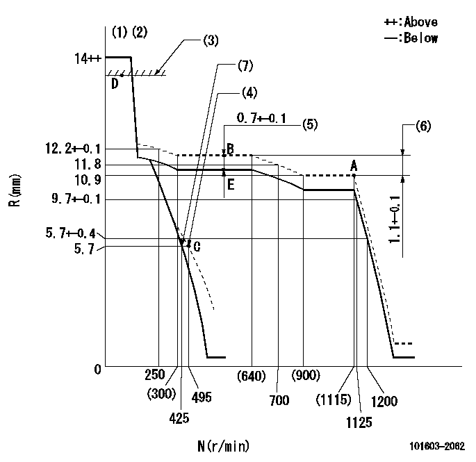
N:Pump speed
R:Rack position (mm)
(1)Target notch: K
(2)Tolerance for racks not indicated: +-0.05mm.
(3)RACK LIMIT
(4)Set idle sub-spring
(5)Boost compensator stroke
(6)Rack difference between N = N1 and N = N2
(7)Main spring setting
----------
K=10 N1=1100r/min N2=500r/min
----------
----------
K=10 N1=1100r/min N2=500r/min
----------
Speed control lever angle

F:Full speed
I:Idle
(1)Stopper bolt setting
----------
----------
a=5deg+-5deg b=23deg+-5deg
----------
----------
a=5deg+-5deg b=23deg+-5deg
Stop lever angle

N:Pump normal
S:Stop the pump.
(1)Speed = aa, rack position = bb (sealed at shipping)
----------
aa=0r/min bb=1-0.2mm
----------
a=21deg+-5deg b=(55deg)
----------
aa=0r/min bb=1-0.2mm
----------
a=21deg+-5deg b=(55deg)
Timing setting

(1)Pump vertical direction
(2)Coupling's key groove position at No 1 cylinder's beginning of injection
(3)-
(4)-
----------
----------
a=(50deg)
----------
----------
a=(50deg)
Information:
(1) Torque for the terminal nuts ... 30 3 N m (22 2 lb ft)(2) Torque for the screws that hold the nose housing to the lever housing ... 20 3 N m (15 2 lb ft)Clearance between the pinion and housing (pinion clearance) ... 8.3 to 9.9 mm (.33 to .39 in)8C3651 24V
Rotation as seen from the drive end ... clockwiseNo load conditions: Speed (rpm) ... 7350 1050Current amps ... 60 to 75Voltage ... 23Used with solenoid ... 7T02584N3180 24V, 2P3926 24V
The two 10-32 screws on the underside of the solenoid are tightened to a torque of ... 2 to 3 N m (16 to 30 lb in)Rotation as seen from the drive end ... clockwiseNo load conditions: Speed (rpm) ... 6000 to 8250Current amps ... 155 15Voltage ... 23Used with solenoid ... 3T34213T2647 24V
The two 10-32 screws on the solenoid are tightened to a torque of ... 2.25 0.25 N m (20 2 lb in)The two 1/2-13 nuts on the solenoid are tightened to a torque of ... 31 4 N m (23 3 lb ft)Rotation as seen from the drive end ... clockwiseNo load conditions: Speed (rpm) ... 8130 2130Current amps ... 89 29Voltage ... 23Used with solenoid ... 7T88543T8946 24V
Rotation as seen from the drive end ... clockwiseNo load conditions: Speed (rpm) ... 6500 1000Current amps ... 107.5 12.5Voltage ... 20Used with solenoid ... 7T88549G4338 24V
Rotation as seen from the drive end ... clockwiseMinimum (no load) speed (rpm) ... 6500Current consumption (draw) at 20V (no load) ... 77A(1) Torque for the housing bolts ... 11 N m (8 lb ft)(2) Torque for the terminal nuts ... 27 to 34 N m (20 to 25 lb ft)(3) Clearance between the pinion and housing ... 0.51 to 1.27 mm (.020 to .050 in)Used with solenoid ... 3T86353T6305 24V
Rotation as seen from the drive end ... clockwiseMaximum (no load) speed (rpm) ... 5500Maximum current consumption (draw) (no load) ... 200A(1) Torque for the large terminal nuts ... 27 to 33 N m (20 to 24 lb ft) Torque for the small terminal nuts ... 4 to 5 N m (35 to 45 lb in)(2) Service limit of brushes ... 17.5 mm (.69 in)(3) Service limit of commutater diameter ... 48 mm (1.9 in)Pinion to ring gear clearance ... 1.5 to 5.5 mm (.06 to .22 in)Used with solenoid ... 9X03329X4447 24V
(1) Torque for terminal nuts: Small terminal nuts ... 2.25 .25 N m (20 2 lb ft)Large terminal nuts ... 30.5 3.5 N m (22.5 2.5 lb ft)No load conditions: Speed (rpm) ... 3300Current amps ... 80AVoltage ... 23.5Used with solenoid ... 3E0135