Information injection-pump assembly
ZEXEL
101603-2060
1016032060
HINO
220204340A
220204340a

Rating:
Cross reference number
ZEXEL
101603-2060
1016032060
HINO
220204340A
220204340a
Zexel num
Bosch num
Firm num
Name
Calibration Data:
Adjustment conditions
Test oil
1404 Test oil ISO4113 or {SAEJ967d}
1404 Test oil ISO4113 or {SAEJ967d}
Test oil temperature
degC
40
40
45
Nozzle and nozzle holder
105780-8140
Bosch type code
EF8511/9A
Nozzle
105780-0000
Bosch type code
DN12SD12T
Nozzle holder
105780-2080
Bosch type code
EF8511/9
Opening pressure
MPa
17.2
Opening pressure
kgf/cm2
175
Injection pipe
Outer diameter - inner diameter - length (mm) mm 6-2-600
Outer diameter - inner diameter - length (mm) mm 6-2-600
Overflow valve
134424-0920
Overflow valve opening pressure
kPa
162
147
177
Overflow valve opening pressure
kgf/cm2
1.65
1.5
1.8
Tester oil delivery pressure
kPa
157
157
157
Tester oil delivery pressure
kgf/cm2
1.6
1.6
1.6
Direction of rotation (viewed from drive side)
Right R
Right R
Injection timing adjustment
Direction of rotation (viewed from drive side)
Right R
Right R
Injection order
1-4-2-6-
3-5
Pre-stroke
mm
4.8
4.77
4.83
Beginning of injection position
Drive side NO.1
Drive side NO.1
Difference between angles 1
Cal 1-4 deg. 60 59.75 60.25
Cal 1-4 deg. 60 59.75 60.25
Difference between angles 2
Cyl.1-2 deg. 120 119.75 120.25
Cyl.1-2 deg. 120 119.75 120.25
Difference between angles 3
Cal 1-6 deg. 180 179.75 180.25
Cal 1-6 deg. 180 179.75 180.25
Difference between angles 4
Cal 1-3 deg. 240 239.75 240.25
Cal 1-3 deg. 240 239.75 240.25
Difference between angles 5
Cal 1-5 deg. 300 299.75 300.25
Cal 1-5 deg. 300 299.75 300.25
Injection quantity adjustment
Adjusting point
A
Rack position
9.5
Pump speed
r/min
1100
1100
1100
Average injection quantity
mm3/st.
85.5
84
87
Max. variation between cylinders
%
0
-3.5
3.5
Basic
*
Fixing the lever
*
Boost pressure
kPa
36
36
Boost pressure
mmHg
270
270
Injection quantity adjustment_02
Adjusting point
-
Rack position
6.4+-0.5
Pump speed
r/min
400
400
400
Average injection quantity
mm3/st.
10
9
11
Max. variation between cylinders
%
0
-10
10
Fixing the rack
*
Boost pressure
kPa
0
0
0
Boost pressure
mmHg
0
0
0
Remarks
Adjust only variation between cylinders; adjust governor according to governor specifications.
Adjust only variation between cylinders; adjust governor according to governor specifications.
Boost compensator adjustment
Pump speed
r/min
600
600
600
Rack position
9.9
Boost pressure
kPa
14.7
12
17.4
Boost pressure
mmHg
110
90
130
Boost compensator adjustment_02
Pump speed
r/min
600
600
600
Rack position
10.5
Boost pressure
kPa
22.7
22.7
22.7
Boost pressure
mmHg
170
170
170
Timer adjustment
Pump speed
r/min
-
Advance angle
deg.
0
0
0
Remarks
Measure speed (beginning of operation).
Measure speed (beginning of operation).
Timer adjustment_02
Pump speed
r/min
-
Advance angle
deg.
2
1.5
2.5
Remarks
Measure the actual speed, stop
Measure the actual speed, stop
Test data Ex:
Governor adjustment
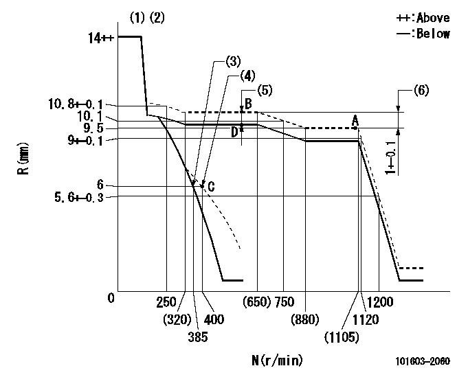
N:Pump speed
R:Rack position (mm)
(1)Target notch: K
(2)Tolerance for racks not indicated: +-0.05mm.
(3)Main spring setting
(4)Set idle sub-spring
(5)Boost compensator stroke: BCL
(6)Rack difference between N = N1 and N = N2
----------
K=16 BCL=0.6+-0.1mm N1=1100r/min N2=600r/min
----------
----------
K=16 BCL=0.6+-0.1mm N1=1100r/min N2=600r/min
----------
Speed control lever angle

F:Full speed
I:Idle
(1)Stopper bolt setting
----------
----------
a=12deg+-5deg b=24deg+-5deg
----------
----------
a=12deg+-5deg b=24deg+-5deg
Stop lever angle

N:Pump normal
S:Stop the pump.
(1)Speed = aa, rack position = bb (sealed at shipping)
----------
aa=0r/min bb=1-0.2mm
----------
a=21deg+-5deg b=(55deg)
----------
aa=0r/min bb=1-0.2mm
----------
a=21deg+-5deg b=(55deg)
Timing setting

(1)Pump vertical direction
(2)Coupling's key groove position at No 1 cylinder's beginning of injection
(3)-
(4)-
----------
----------
a=(50deg)
----------
----------
a=(50deg)
Information:
(1) Thickness of spacer plate ... 9.970 0.025 mm (.3925 .0010 in) Thickness of spacer plate gasket ... 0.208 0.025 mm (.0082 .0010 in) For height of liner over top of spacer plate make reference to Cylinder Liner Projection.(2) Camshaft bearing bore (installed) ... 58.80 0.06 mm (2.315 .002 in) Bore in block for camshaft bearings ... 65.100 0.025 mm (2.5630 .0010 in)(3) Bore in block for main bearings (standard size) ... 96.926 0.013 mm (3.8160 .0005 in) Bore in block for main bearings 0.51 mm (.020 in) oversize ... 97.436 0.013 mm (3.8361 .0005 in)(4) Dimension from center of main bearing bore to top of cylinder block (new) ... 383.515 0.165 mm (15.099 .0065 in)(5) Dimension from center of main bearing bore to bottom of cylinder block (new) 153.99 0.10 mm (6.063 .004 in)(6) Torque for bolts holding bearing caps for main bearings: a. Put 2P2506 Thread Lubricant on threads and washer face.b. Tighten all bolts to ... 41 4 N m (30 3 lb ft)c. Put a mark on each bolt and cap.d. Tighten all bolts from mark ... 90 5° Install bearing caps with the part number toward the front of the engine. Be sure that the mark (number) on the bearing cap next to the bolt hole is in agreement with the mark in the cylinder block.(7) Clearance between main bearing cap and cylinder block ... 0.033 mm (.0013 in) tight to ... 0.043 mm (.0017 in) looseMain bearing cap width ... 165.095 0.020 mm (6.4998 .0008 in)Width of cylinder block for main bearing cap ... 165.100 0.018 mm (6.5000 .0007 in) (8) Piston cooling orifice.
There are holes in the bores for the main bearings, between the cylinders for piston cooling orifices. These holes must have orifices (8) installed.
(9) Distance two dowels extend from the surface of the cylinder block ... 19.8 0.5 mm (.78 .02 in)(10) Distance hollow dowel extends from the surface of the cylinder block ... 16.0 0.5 mm (.63 .02 in)(11) Depth to install two dowels below the surface of the cylinder block (apply Loctite #11358) ... 1.0 0.5 mm (.04 .02 in)(12) Distance dowels extend from the front face of the cylinder block ... 22.4 0.5 mm (.88 .02 in)(13) Distance stud extends from the front face of the cylinder block ... 15.7 0.5 mm (.62 .02 in)(14) Distance two dowels extend from the rear face of the cylinder block ... 12.7 0.5 mm (.50 .02 in)