Information injection-pump assembly
ZEXEL
101603-2033
1016032033
HINO
220204122A
220204122a
Rating:
Service parts 101603-2033 INJECTION-PUMP ASSEMBLY:
1.
_
7.
COUPLING PLATE
8.
_
9.
_
11.
Nozzle and Holder
23600-2490A
12.
Open Pre:MPa(Kqf/cm2)
19.6{200}
15.
NOZZLE SET
Cross reference number
ZEXEL
101603-2033
1016032033
HINO
220204122A
220204122a
Zexel num
Bosch num
Firm num
Name
Calibration Data:
Adjustment conditions
Test oil
1404 Test oil ISO4113 or {SAEJ967d}
1404 Test oil ISO4113 or {SAEJ967d}
Test oil temperature
degC
40
40
45
Nozzle and nozzle holder
105780-8140
Bosch type code
EF8511/9A
Nozzle
105780-0000
Bosch type code
DN12SD12T
Nozzle holder
105780-2080
Bosch type code
EF8511/9
Opening pressure
MPa
17.2
Opening pressure
kgf/cm2
175
Injection pipe
Outer diameter - inner diameter - length (mm) mm 6-2-600
Outer diameter - inner diameter - length (mm) mm 6-2-600
Overflow valve
134424-0920
Overflow valve opening pressure
kPa
162
147
177
Overflow valve opening pressure
kgf/cm2
1.65
1.5
1.8
Tester oil delivery pressure
kPa
157
157
157
Tester oil delivery pressure
kgf/cm2
1.6
1.6
1.6
Direction of rotation (viewed from drive side)
Right R
Right R
Injection timing adjustment
Direction of rotation (viewed from drive side)
Right R
Right R
Injection order
1-4-2-6-
3-5
Pre-stroke
mm
4.8
4.77
4.83
Beginning of injection position
Drive side NO.1
Drive side NO.1
Difference between angles 1
Cal 1-4 deg. 60 59.75 60.25
Cal 1-4 deg. 60 59.75 60.25
Difference between angles 2
Cyl.1-2 deg. 120 119.75 120.25
Cyl.1-2 deg. 120 119.75 120.25
Difference between angles 3
Cal 1-6 deg. 180 179.75 180.25
Cal 1-6 deg. 180 179.75 180.25
Difference between angles 4
Cal 1-3 deg. 240 239.75 240.25
Cal 1-3 deg. 240 239.75 240.25
Difference between angles 5
Cal 1-5 deg. 300 299.75 300.25
Cal 1-5 deg. 300 299.75 300.25
Injection quantity adjustment
Adjusting point
A
Rack position
11.6
Pump speed
r/min
1050
1050
1050
Average injection quantity
mm3/st.
117
115.5
118.5
Max. variation between cylinders
%
0
-3.5
3.5
Basic
*
Fixing the lever
*
Boost pressure
kPa
35.3
35.3
Boost pressure
mmHg
265
265
Injection quantity adjustment_02
Adjusting point
-
Rack position
6.2+-0.5
Pump speed
r/min
430
430
430
Average injection quantity
mm3/st.
10
9
11
Max. variation between cylinders
%
0
-10
10
Fixing the rack
*
Boost pressure
kPa
0
0
0
Boost pressure
mmHg
0
0
0
Remarks
Adjust only variation between cylinders; adjust governor according to governor specifications.
Adjust only variation between cylinders; adjust governor according to governor specifications.
Injection quantity adjustment_03
Adjusting point
D
Rack position
-
Pump speed
r/min
100
100
100
Average injection quantity
mm3/st.
140
140
150
Fixing the lever
*
Boost pressure
kPa
0
0
0
Boost pressure
mmHg
0
0
0
Rack limit
*
Boost compensator adjustment
Pump speed
r/min
800
800
800
Rack position
R1-1.2
Boost pressure
kPa
8.7
6
11.4
Boost pressure
mmHg
65
45
85
Boost compensator adjustment_02
Pump speed
r/min
800
800
800
Rack position
R1(11.6)
Boost pressure
kPa
22
15.3
28.7
Boost pressure
mmHg
165
115
215
Timer adjustment
Pump speed
r/min
850--
Advance angle
deg.
0
0
0
Remarks
Start
Start
Timer adjustment_02
Pump speed
r/min
800
Advance angle
deg.
0.5
Timer adjustment_03
Pump speed
r/min
1050
Advance angle
deg.
2
1.5
2.5
Remarks
Finish
Finish
Test data Ex:
Governor adjustment
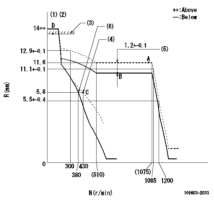
N:Pump speed
R:Rack position (mm)
(1)Target notch: K
(2)Tolerance for racks not indicated: +-0.05mm.
(3)RACK LIMIT
(4)Set idle sub-spring
(5)Boost compensator stroke
(6)Main spring setting
----------
K=16
----------
----------
K=16
----------
Speed control lever angle

F:Full speed
I:Idle
(1)Stopper bolt setting
----------
----------
a=16deg+-5deg b=28deg+-5deg
----------
----------
a=16deg+-5deg b=28deg+-5deg
Stop lever angle

N:Pump normal
S:Stop the pump.
(1)Speed = aa, rack position = bb (sealed at shipping)
(2)Normal
----------
aa=0r/min bb=1-0.5mm
----------
a=21deg+-5deg b=(55deg)
----------
aa=0r/min bb=1-0.5mm
----------
a=21deg+-5deg b=(55deg)
Timing setting

(1)Pump vertical direction
(2)Coupling's key groove position at No 1 cylinder's beginning of injection
(3)-
(4)-
----------
----------
a=(50deg)
----------
----------
a=(50deg)
Information:
Power Plug To Chassis Harness
Connect 777-PU wire to 777-PU wire on chassis harness.Starter Connections
The connector with the plug in Loc. 3, connects to the bottom starter. The connector without the plug in Loc. 3, goes to the top starter.Air Conditioner (Attachment).
8C9677 Harness Assembly1. Install 8C9677 Harness Assembly to the air conditioner (513-OR and 200-BK).2. Remove plug housing from the EUI engine harness and connect the 2 pin sure seal breakout to 8C9677 Air Conditioner Harness Assembly.Steering Flow Switch.
Connect the 2 pin sure seal breakout to the steering flow switch.Ether System
* Trucks equipped with auto ether system with Multi-Point Oil Pressure Sensing perform the following steps:
8X5415 Wire AssemblyRemove the code plug installed in the chassis auto ether harness on top of the left fore-aft beam near the cab and replace it with 8X5415 Wire Assembly. This disables the multi-point oil pressure function.Remove the engine oil pressure sensor control and its hardware on the right rear of the engine. It will be replaced by the oil pressure sensor for the EUI system.* Trucks with auto ether system where the ether coolant sensor is located in the water regulator housing on the left side of the engine perform the following steps: If the truck has the ether coolant sensor in location (A), the new EUI cover (7E5326) must be reworkedThe bottom right port (B) must be changed to No. 6 Port. Drill and tape for (9/16-18-2B threads).Move the ether coolant sensor to location (B), new No. Port 6. Relocate the connector clip to the lower right bolt of the cover if necessary to retain connection.Tachograph Group
8X8529 Tachometer Group (1) 4N3695 Cable Assembly. (2) Two 338248 Clips. (3) 5M3062 Bolt. (4) 8T4896 Washer.1. Install the 8X8529 Tachometer Drive Group as shown in the illustration above.Tighten the tach cable to 11.3 1.8 N m (100.0 15.9 lb in) at the engine end and 5.7 0.9 N m (50.4 8.0 lb in) at the cab end.2. This completes the EUI retro-fit installation.3. Clean and paint all welded areas.4. Secure all harnesses and wires with tie wraps.5. Check all areas that were modified or changed.6. Connect the batteries.Description Of New Lamps And Switches On New Dash Plate
* CHECK ENGINE LAMP (1)This lamp is used to indicate when a problem exists in the engines electronic control systemThe indicator will come on when the start switch is in the ON position and the engine is not operating. The lamp will stay on approximately 5 seconds, then go out.This lamp is also used to read diagnostic flash codes in conjunction with the diagnostic enable switch.* AIR FILTER RESTRICTION LAMP (2)This lamp indicates that the engine air intake filters are plugged.If the indicator comes on, service the filters that day.* ENGINE OVERSPEED LAMP (3)This lamp indicates the engine rpm is too high. The engine overspeed alarm will sound also when the engine is exceeding maximum allowable limit for safe operation. The lamp and alarm will remain ON as long as the engine is overspeeding.* THROTTLE