Information injection-pump assembly
ZEXEL
101603-2031
1016032031
HINO
220204120B
220204120b
Rating:
Service parts 101603-2031 INJECTION-PUMP ASSEMBLY:
1.
_
7.
COUPLING PLATE
8.
_
9.
_
11.
Nozzle and Holder
23600-2490A
12.
Open Pre:MPa(Kqf/cm2)
19.6{200}
15.
NOZZLE SET
Cross reference number
ZEXEL
101603-2031
1016032031
HINO
220204120B
220204120b
Zexel num
Bosch num
Firm num
Name
Calibration Data:
Adjustment conditions
Test oil
1404 Test oil ISO4113 or {SAEJ967d}
1404 Test oil ISO4113 or {SAEJ967d}
Test oil temperature
degC
40
40
45
Nozzle and nozzle holder
105780-8140
Bosch type code
EF8511/9A
Nozzle
105780-0000
Bosch type code
DN12SD12T
Nozzle holder
105780-2080
Bosch type code
EF8511/9
Opening pressure
MPa
17.2
Opening pressure
kgf/cm2
175
Injection pipe
Outer diameter - inner diameter - length (mm) mm 6-2-600
Outer diameter - inner diameter - length (mm) mm 6-2-600
Overflow valve
134424-0920
Overflow valve opening pressure
kPa
162
147
177
Overflow valve opening pressure
kgf/cm2
1.65
1.5
1.8
Tester oil delivery pressure
kPa
157
157
157
Tester oil delivery pressure
kgf/cm2
1.6
1.6
1.6
Direction of rotation (viewed from drive side)
Right R
Right R
Injection timing adjustment
Direction of rotation (viewed from drive side)
Right R
Right R
Injection order
1-4-2-6-
3-5
Pre-stroke
mm
4.8
4.77
4.83
Beginning of injection position
Drive side NO.1
Drive side NO.1
Difference between angles 1
Cal 1-4 deg. 60 59.75 60.25
Cal 1-4 deg. 60 59.75 60.25
Difference between angles 2
Cyl.1-2 deg. 120 119.75 120.25
Cyl.1-2 deg. 120 119.75 120.25
Difference between angles 3
Cal 1-6 deg. 180 179.75 180.25
Cal 1-6 deg. 180 179.75 180.25
Difference between angles 4
Cal 1-3 deg. 240 239.75 240.25
Cal 1-3 deg. 240 239.75 240.25
Difference between angles 5
Cal 1-5 deg. 300 299.75 300.25
Cal 1-5 deg. 300 299.75 300.25
Injection quantity adjustment
Adjusting point
A
Rack position
11.5
Pump speed
r/min
1050
1050
1050
Average injection quantity
mm3/st.
120
118.5
121.5
Max. variation between cylinders
%
0
-3.5
3.5
Basic
*
Fixing the lever
*
Boost pressure
kPa
35.3
35.3
Boost pressure
mmHg
265
265
Injection quantity adjustment_02
Adjusting point
-
Rack position
6.3
Pump speed
r/min
400
400
400
Average injection quantity
mm3/st.
10
9
11
Max. variation between cylinders
%
0
-10
10
Fixing the rack
*
Boost pressure
kPa
0
0
0
Boost pressure
mmHg
0
0
0
Remarks
Adjust only variation between cylinders; adjust governor according to governor specifications.
Adjust only variation between cylinders; adjust governor according to governor specifications.
Boost compensator adjustment
Pump speed
r/min
725
725
725
Rack position
10.3
Boost pressure
kPa
8.7
6
11.4
Boost pressure
mmHg
65
45
85
Boost compensator adjustment_02
Pump speed
r/min
725
725
725
Rack position
(11.5)
Boost pressure
kPa
22
15.3
28.7
Boost pressure
mmHg
165
115
215
Timer adjustment
Pump speed
r/min
850--
Advance angle
deg.
0
0
0
Remarks
Start
Start
Timer adjustment_02
Pump speed
r/min
800
Advance angle
deg.
0.5
Timer adjustment_03
Pump speed
r/min
1050
Advance angle
deg.
2
1.5
2.5
Remarks
Finish
Finish
Test data Ex:
Governor adjustment
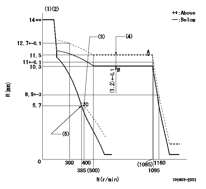
N:Pump speed
R:Rack position (mm)
(1)Notch fixed: K
(2)Tolerance for racks not indicated: +-0.05mm.
(3)Set idle sub-spring
(4)Boost compensator stroke
(5)Main spring setting
----------
K=17
----------
----------
K=17
----------
Speed control lever angle

F:Full speed
I:Idle
(1)Stopper bolt setting
----------
----------
a=(17deg)+-5deg b=(28deg)+-5deg
----------
----------
a=(17deg)+-5deg b=(28deg)+-5deg
Stop lever angle

N:Pump normal
S:Stop the pump.
(1)Speed = aa, rack position = bb (sealed at shipping)
----------
aa=0r/min bb=1-0.5mm
----------
a=21deg+-5deg b=(55deg)
----------
aa=0r/min bb=1-0.5mm
----------
a=21deg+-5deg b=(55deg)
Timing setting

(1)Pump vertical direction
(2)Coupling's key groove position at No 1 cylinder's beginning of injection
(3)-
(4)-
----------
----------
a=(50deg)
----------
----------
a=(50deg)
Information:
2. Locate wire 405-GY on the main cab harness near the connector exiting the cab wall on the right hand side, as shown by arrow.Cut this wire close to the connector. Splice it and the wire just assembled using an 8S4626 Splice. Be sure to splice to the portion of the wire that goes into the cab harness.3. Connect the 7N9738 Housing to the two pin connector on the 8X9862 Harness Assembly (housing containing 405-GY). Clip with a 3T3048 Clip Assembly.Installation of Ether (Chassis) Wiring Harness
The ether chassis harness for MPPS is different than the one called out in the AEIS Special Instruction.* Substitute 8X8468 Harness Assembly for 8X7653 Harness Assembly on the 785 Trucks.* Substitute 8X8467 Harness Assembly for 8X7652 Harness Assembly on the 789 Trucks.Follow the installation procedure outlined in the AEIS Special Instruction for the Ether Chassis Harness Assembly. Be sure to use the 8X8466 Wire Assembly for the 785 Trucks or the 8X8429 Wire Assembly for the 789 Trucks. This is the new harness code plug required with MPPS.Installation of 8X8469 Ether (Engine) Wiring Harness
The 8X7106 Engine Harness on the AEIS is replaced with 8X8469 Harness Assembly.Follow the installation procedure outlined in the AEIS Special Instruction for the 8X7106 Harness Assembly. In addition, the following steps need to be performed. 1. Route the end of the harness with the 8T8732 Receptacle to the 3E3530 Electronic Control Group (oil pressure sensor) installed at the right rear of the engine as shown.2. Connect the three pin receptacle to the connector on the 3E3530 Electronic Control Group (2) and clip into the 9X3495 Clip Assembly (7) installed earlier. Use 3S2093 Straps (8) to loosely secure the harness to the top rear of the engine as shown.3. Remove the 8W3048 Harness Assembly that is connected to the remaining 6T7663 Oil Pressure Switch (9) and was connected to the 6T7663 Oil Pressure Switch (9) that was removed.4. Connect an 8X8337 Harness Assembly (10) to the one remaining oil pressure switch and reconnect to the engine harness. Clip with the existing clip. DO NOT tighten the straps or clips until all new wiring harnesses have been installed so any repositioning or adjustments can be made as necessary.Checking the Automatic Ether Injection System
* The system check-out will be same as for the AEIS with the following change: "A5" harness code on the 785 (indicates 3512 application) or "A6" harness code on the 789 (indicates 3516 application) for two seconds.Retrofit to an Existing AEIS System
Necessary Parts
Installation of 3E3778 Ether Control Group
The 3E3778 Control Group is required for the MPPS System.Check the electronic control box installed with the AEIS to see if it is a 3E3778 or a 9X5303 Control Group. If a 9X5303 control Group is installed, replace it with 3E3778 Control Group and 3E3779 Film.Follow the "Installation of 9X5303 Ether Control Group" instructions outlined in the AEIS installation Special Instruction, SEHS9293. Be sure to install the 8X8398 Wire Assembly between the control and mounting plate. If an MPPS identification film is