Information injection-pump assembly
ZEXEL
101603-2020
1016032020
HINO
220008070A
220008070a
Rating:
Service parts 101603-2020 INJECTION-PUMP ASSEMBLY:
1.
_
6.
COUPLING PLATE
7.
COUPLING PLATE
8.
_
9.
_
11.
Nozzle and Holder
23600-2142A
12.
Open Pre:MPa(Kqf/cm2)
19.6{200}
15.
NOZZLE SET
Cross reference number
ZEXEL
101603-2020
1016032020
HINO
220008070A
220008070a
Zexel num
Bosch num
Firm num
Name
Calibration Data:
Adjustment conditions
Test oil
1404 Test oil ISO4113 or {SAEJ967d}
1404 Test oil ISO4113 or {SAEJ967d}
Test oil temperature
degC
40
40
45
Nozzle and nozzle holder
105780-8140
Bosch type code
EF8511/9A
Nozzle
105780-0000
Bosch type code
DN12SD12T
Nozzle holder
105780-2080
Bosch type code
EF8511/9
Opening pressure
MPa
17.2
Opening pressure
kgf/cm2
175
Injection pipe
Outer diameter - inner diameter - length (mm) mm 6-2-600
Outer diameter - inner diameter - length (mm) mm 6-2-600
Overflow valve
134424-0920
Overflow valve opening pressure
kPa
162
147
177
Overflow valve opening pressure
kgf/cm2
1.65
1.5
1.8
Tester oil delivery pressure
kPa
157
157
157
Tester oil delivery pressure
kgf/cm2
1.6
1.6
1.6
Direction of rotation (viewed from drive side)
Right R
Right R
Injection timing adjustment
Direction of rotation (viewed from drive side)
Right R
Right R
Injection order
1-4-2-6-
3-5
Pre-stroke
mm
3.45
3.42
3.48
Beginning of injection position
Drive side NO.1
Drive side NO.1
Difference between angles 1
Cal 1-4 deg. 60 59.75 60.25
Cal 1-4 deg. 60 59.75 60.25
Difference between angles 2
Cyl.1-2 deg. 120 119.75 120.25
Cyl.1-2 deg. 120 119.75 120.25
Difference between angles 3
Cal 1-6 deg. 180 179.75 180.25
Cal 1-6 deg. 180 179.75 180.25
Difference between angles 4
Cal 1-3 deg. 240 239.75 240.25
Cal 1-3 deg. 240 239.75 240.25
Difference between angles 5
Cal 1-5 deg. 300 299.75 300.25
Cal 1-5 deg. 300 299.75 300.25
Injection quantity adjustment
Adjusting point
-
Rack position
11.2
Pump speed
r/min
900
900
900
Average injection quantity
mm3/st.
58.8
56.8
60.8
Max. variation between cylinders
%
0
-3.5
3.5
Basic
*
Fixing the rack
*
Standard for adjustment of the maximum variation between cylinders
*
Injection quantity adjustment_02
Adjusting point
H
Rack position
9.3+-0.5
Pump speed
r/min
250
250
250
Each cylinder's injection qty
mm3/st.
17.1
16.1
18.1
Fixing the rack
*
Standard for adjustment of the maximum variation between cylinders
*
Injection quantity adjustment_03
Adjusting point
A
Rack position
R1(11.2)
Pump speed
r/min
900
900
900
Average injection quantity
mm3/st.
58.8
57.8
59.8
Basic
*
Fixing the lever
*
Injection quantity adjustment_04
Adjusting point
B
Rack position
R1(11.2)
Pump speed
r/min
1500
1500
1500
Average injection quantity
mm3/st.
59.3
55.3
63.3
Fixing the lever
*
Injection quantity adjustment_05
Adjusting point
C
Rack position
R1+0.3
Pump speed
r/min
600
600
600
Average injection quantity
mm3/st.
53.7
49.7
57.7
Fixing the lever
*
Injection quantity adjustment_06
Adjusting point
I
Rack position
-
Pump speed
r/min
100
100
100
Average injection quantity
mm3/st.
123
123
133
Fixing the lever
*
Rack limit
*
Timer adjustment
Pump speed
r/min
1050--
Advance angle
deg.
0
0
0
Remarks
Start
Start
Timer adjustment_02
Pump speed
r/min
1000
Advance angle
deg.
0.3
Timer adjustment_03
Pump speed
r/min
1500
Advance angle
deg.
2.5
2.2
2.8
Remarks
Finish
Finish
Test data Ex:
Governor adjustment
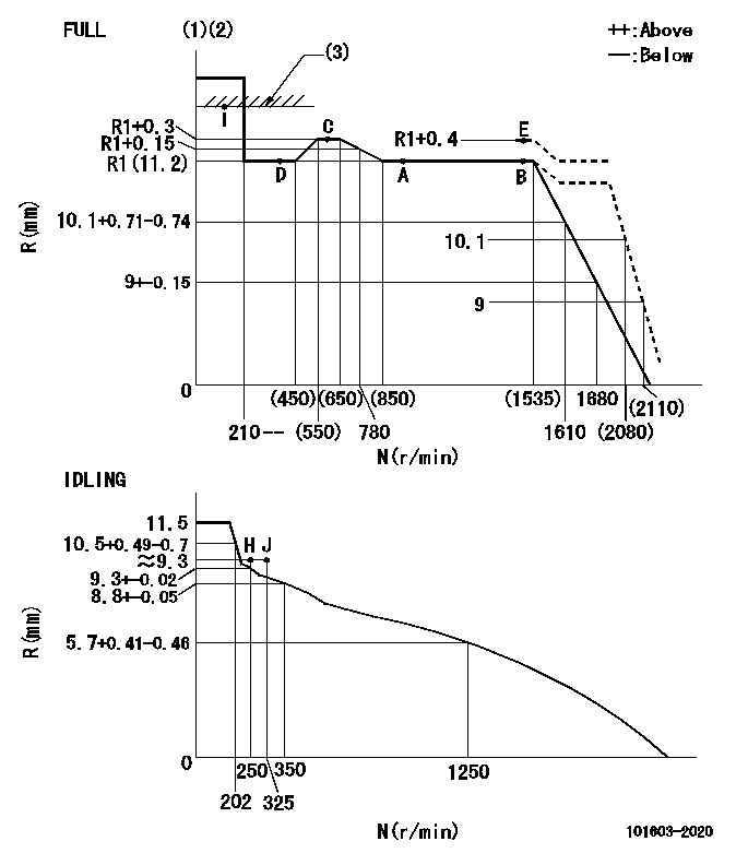
N:Pump speed
R:Rack position (mm)
(1)Torque cam stamping: T1
(2)Tolerance for racks not indicated: +-0.05mm.
(3)RACK LIMIT
----------
T1=H37
----------
----------
T1=H37
----------
Speed control lever angle
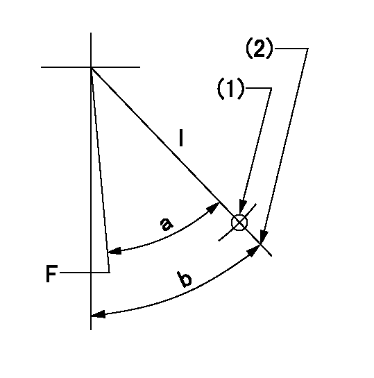
F:Full speed
I:Idle
(1)Use the hole at R = aa
(2)Stopper bolt set position 'H'
----------
aa=55mm
----------
a=(27deg)+-3deg b=34deg+-5deg
----------
aa=55mm
----------
a=(27deg)+-3deg b=34deg+-5deg
Stop lever angle
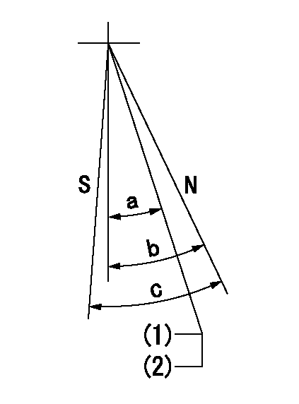
N:Pump normal
S:Stop the pump.
(1)Rack position = aa
(2)Set the stopper bolt. (After setting, apply red paint.)
----------
aa=17+-0.1mm
----------
a=(35deg) b=40deg+-5deg c=40deg+-5deg
----------
aa=17+-0.1mm
----------
a=(35deg) b=40deg+-5deg c=40deg+-5deg
0000001501 TAMPER PROOF
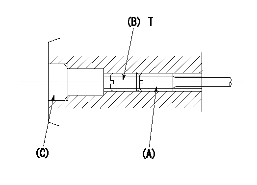
1. Method for setting tamperproof proofing
(1)After governor adjustment (torque cam phase adjustment), move the load lever to increase the full rack position to Ra.
(2)At pump speed N1, push in the screw (A) until the rack position is Rb.
(3)Temporarily caulk using the tip of a screwdriver
(4)Confirm that the rack at that time is at Rc.
(5)Lock using setscrew (B). (Tightening torque = T)
(6)Next, coat (C) with adhesive and then pressfit.
(7)Then, readjust the full rack position using the load lever.
----------
N1=1500r/min Ra=R1(11.2)+0.4mm Rb=R1(11.2)+0.4mm Rc=R1(11.2)+0.4mm
----------
T=3.4~4.9N-m(0.35~0.5Kgf-m)
----------
N1=1500r/min Ra=R1(11.2)+0.4mm Rb=R1(11.2)+0.4mm Rc=R1(11.2)+0.4mm
----------
T=3.4~4.9N-m(0.35~0.5Kgf-m)
Timing setting

(1)Pump vertical direction
(2)Position of gear's standard threaded hole at No 1 cylinder's beginning of injection
(3)-
(4)-
----------
----------
a=(70deg)
----------
----------
a=(70deg)
Information:
789 Truck
On the 789 Truck, there are two mounting plates and two sets of ether nozzles, both of which are mounted on the frame cross tube in the engine compartment. 1. Install 8X0913 Tube (63) in the front nozzle, and 8W8177 Tube (65) in the rear nozzle of the front pair of turbocharger outlet adapters as shown.2. Use two 5P6314 Sleeves with 5P6313 Nuts to connect tubes (63) and (65) to 8C9006 Tee (64).3. Put 8X5015 Tube (60) in position along the cylinder block and frame cross tube (59). Use a 5P6314 Sleeve and a 5P6313 Nut to connect tube (60) to 8C9006 Tee (64) as shown.4. Connect one end of a 7N0140 Tube Assembly in the bottom of the shuttle valve on the right side mounting plate (62) to the free end of 8X5015 Tube (60).5. Use three 6V2686 Clips (61), with existing bolts on the engine cylinder block and truck frame cross tube (59), to secure 8X5015 Tube (60) as shown.6. Install 8W8179 Tube (66) in the front nozzle and 8W8180 Tube (67) in the rear nozzle of the rear pair of turbocharger outlet adapters as shown.7. Use two 5P6314 Sleeves with 5P6313 Nuts to connect tubes (66) and (67) to 8C9006 Tee (68).8. Use two 6V2686 Clips (61) with existing bolts to secure 8W8180 Tube (67) to the engine block as shown.9. Put 8W8178 Tube (69) in position along the cylinder block and connect it to 8C9006 Tee (68) as shown using a 5P6314 Sleeve and 5P6313 Nut.10. Connect one end of a 7N0140 Tube Assembly in the bottom connector of the shuttle valve on left side mounting plate (70) to the free end of the 8W8178 Tube (69).11. Use three 6V2686 Clips (61) with existing bolts on engine cylinder block to secure 8W8178 Tube (69) as shown.Installation of Ether Cylinders
1. Turn the disconnect switch to the ON position and put the start switch key in the OFF position. Make sure the two lamps on the console and the two yellow LEDs on the ECU are flashing.If they are flashing, it indicates that the control is functioning and recognizes that no ether cylinders are installed.2. Inspect the two digit, seven segment LED display on the ECU. It must read "00". This in an indication that there are no faults.If the display does not read "00", refer to the Service Manual, SENR4705, for a troubleshooting procedure of the system. 3. Remove protective caps (71) and (72) from 9X7137 Ether Solenoid Valves (73) and (74) (left side ether assembly mounting plate on 789 Truck when viewed from the rear of the engine). Install a new 9X7138 Filter Assembly in each solenoid valve inlet if one is not already in place.4. Install a 9X0147 Collar on the neck of each new 7X1062 Ether Cylinder.5. Remove the protective plug from the end of the new FULL ether cylinder, then install the new ether cylinder for ether