Information injection-pump assembly
BOSCH
9 400 615 031
9400615031
ZEXEL
101603-1970
1016031970
MITSUBISHI
ME037855
me037855
Rating:
Service parts 101603-1970 INJECTION-PUMP ASSEMBLY:
1.
_
6.
COUPLING PLATE
7.
COUPLING PLATE
8.
_
9.
_
11.
Nozzle and Holder
ME036780
12.
Open Pre:MPa(Kqf/cm2)
21.6{220}

15.
NOZZLE SET
Cross reference number
BOSCH
9 400 615 031
9400615031
ZEXEL
101603-1970
1016031970
MITSUBISHI
ME037855
me037855
Zexel num
Bosch num
Firm num
Name
9 400 615 031
ME037855 MITSUBISHI
INJECTION-PUMP ASSEMBLY
6D14CT K 14BE INJECTION PUMP ASSY PE6A PE
6D14CT K 14BE INJECTION PUMP ASSY PE6A PE
Calibration Data:
Adjustment conditions
Test oil
1404 Test oil ISO4113 or {SAEJ967d}
1404 Test oil ISO4113 or {SAEJ967d}
Test oil temperature
degC
40
40
45
Nozzle and nozzle holder
105780-8140
Bosch type code
EF8511/9A
Nozzle
105780-0000
Bosch type code
DN12SD12T
Nozzle holder
105780-2080
Bosch type code
EF8511/9
Opening pressure
MPa
17.2
Opening pressure
kgf/cm2
175
Injection pipe
Outer diameter - inner diameter - length (mm) mm 6-2-600
Outer diameter - inner diameter - length (mm) mm 6-2-600
Overflow valve
131424-3720
Overflow valve opening pressure
kPa
255
221
289
Overflow valve opening pressure
kgf/cm2
2.6
2.25
2.95
Tester oil delivery pressure
kPa
157
157
157
Tester oil delivery pressure
kgf/cm2
1.6
1.6
1.6
Direction of rotation (viewed from drive side)
Left L
Left L
Injection timing adjustment
Direction of rotation (viewed from drive side)
Left L
Left L
Injection order
1-5-3-6-
2-4
Pre-stroke
mm
3.3
3.25
3.35
Beginning of injection position
Governor side NO.1
Governor side NO.1
Difference between angles 1
Cal 1-5 deg. 60 59.5 60.5
Cal 1-5 deg. 60 59.5 60.5
Difference between angles 2
Cal 1-3 deg. 120 119.5 120.5
Cal 1-3 deg. 120 119.5 120.5
Difference between angles 3
Cal 1-6 deg. 180 179.5 180.5
Cal 1-6 deg. 180 179.5 180.5
Difference between angles 4
Cyl.1-2 deg. 240 239.5 240.5
Cyl.1-2 deg. 240 239.5 240.5
Difference between angles 5
Cal 1-4 deg. 300 299.5 300.5
Cal 1-4 deg. 300 299.5 300.5
Injection quantity adjustment
Adjusting point
A
Rack position
10
Pump speed
r/min
700
700
700
Average injection quantity
mm3/st.
80.3
79.3
81.3
Max. variation between cylinders
%
0
-2.5
2.5
Basic
*
Fixing the lever
*
Injection quantity adjustment_02
Adjusting point
C
Rack position
7.6+-0.5
Pump speed
r/min
375
375
375
Average injection quantity
mm3/st.
9.7
8.2
11.2
Max. variation between cylinders
%
0
-15
15
Fixing the rack
*
Timer adjustment
Pump speed
r/min
1200++
Advance angle
deg.
0
0
0
Remarks
Do not advance until starting N = 1200.
Do not advance until starting N = 1200.
Timer adjustment_02
Pump speed
r/min
-
Advance angle
deg.
2
1.5
2.5
Remarks
Measure the actual speed, stop
Measure the actual speed, stop
Test data Ex:
Governor adjustment
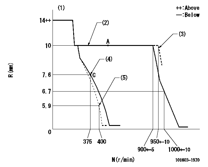
N:Pump speed
R:Rack position (mm)
(1)Target notch: K
(2)Idle spring not operating.
(3)At shipping
(4)Set idle sub-spring
(5)Main spring setting
----------
K=10
----------
----------
K=10
----------
Speed control lever angle
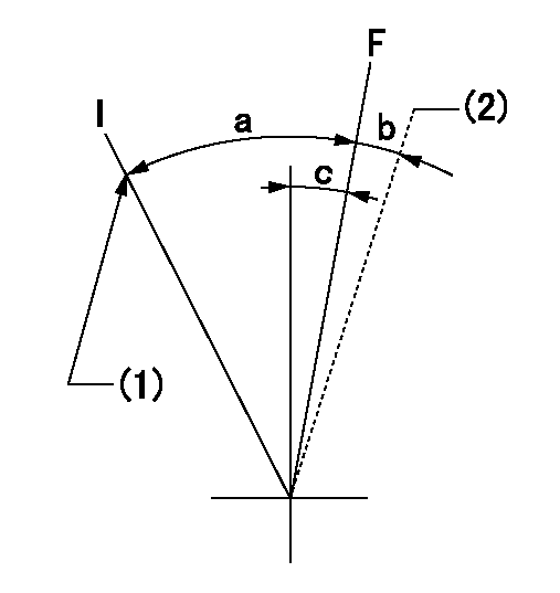
F:Full speed
I:Idle
(1)Stopper bolt setting
(2)At shipping
----------
----------
a=16deg+-5deg b=(7deg) c=6deg+-5deg
----------
----------
a=16deg+-5deg b=(7deg) c=6deg+-5deg
Stop lever angle

N:Pump normal
S:Stop the pump.
----------
----------
a=26deg+-5deg b=53deg+-5deg
----------
----------
a=26deg+-5deg b=53deg+-5deg
Timing setting

(1)Pump vertical direction
(2)Position of gear mark '2' at No 1 cylinder's beginning of injection
(3)B.T.D.C.: aa
(4)-
----------
aa=18deg
----------
a=(90deg)
----------
aa=18deg
----------
a=(90deg)
Information:
1. Remove the pickup from the injection line. Check to be sure the pickup and injection line are clean and dry. The inner bore of the pickup that contacts the injection line must be clean and dry. If necessary, clean the inner bore with a soft dry cloth. If the pickup is damp, dry it in an oven at approximately 50°C (122°F) before reinstalling on the fuel injection line.2. Check the fuel injection line on which the pickup was installed. Make sure all paint has been removed from around the line and that clean bare metal is exposed. Use fine emery paper to clean the line if necessary.3. Reinstall the pickup on the fuel injection line. Make sure the thumbscrew is tight and the pickup is not touching anything except the line. Observe the NO INPUT SIGNAL light and the digital readout on the multitach. If the light stays on bright all the time and the digital display reads 0 when the engine is running, the pickup is not operating. Remove the pickup and amplifier, and test the pickup and amplifier as shown on pages 6 and 7, or use a different pickup and amplifier.4. If the pickup is operating but the NO INPUT SIGNAL light and digital readout are erratic, the pickup output signal is either too low or it is noisy. Run the engine at low and high speeds. If the output signal is too low, the pickup will operate better at high engine speeds. If the signal is noisy, the pickup will usually perform better at low engine speeds. To correct either of these problems, loosen the thumbscrew and rotate the pickup to a new position on the line. Tighten the thumbscrew. Check to see if this solves the problem. To correct noisy operation, it may also be necessary to remove the pickup and reverse it 180° so the signal line points in the opposite direction.5. If pickup operation is still erratic after performing the previous steps, move the pickup to a new location on the same line or to a different line. Make sure each new location is properly prepared before installing pickup. To correct noisy operation (erratic signal and high speed readings), try a pickup location as close as possible to a point where the injection line is fastened to the engine.(D) Use Of The Pickup During Wet Conditions
If the pickup becomes wet, it may operate intermittently or not at all. Although the pickup is water resistant, it is not waterproof. Water spray from rain or other sources may cause the pickup to stop producing an output signal. If this happens, the pickup should be removed from the engine and allowed to dry out thoroughly. If necessary, the pickup can be dried in an oven at approximately 50°C (122°F). After drying, the pickup should operate correctly. If it is not possible to keep the pickup dry, use the following procedure. If the pickup must be used during wet conditions, it may be possible
If the pickup becomes wet, it may operate intermittently or not at all. Although the pickup is water resistant, it is not waterproof. Water spray from rain or other sources may cause the pickup to stop producing an output signal. If this happens, the pickup should be removed from the engine and allowed to dry out thoroughly. If necessary, the pickup can be dried in an oven at approximately 50°C (122°F). After drying, the pickup should operate correctly. If it is not possible to keep the pickup dry, use the following procedure. If the pickup must be used during wet conditions, it may be possible