Information injection-pump assembly
BOSCH
9 400 610 250
9400610250
ZEXEL
101603-1790
1016031790
MITSUBISHI
ME059604
me059604
Rating:
Compare Prices: .
As an associate, we earn commssions on qualifying purchases through the links below

£1,736.83
22 Jul 2018
Robert Bos: Robert Bosch GmbH Au
Bosch 9400610250 Fuel-Injection Pump
Service parts 101603-1790 INJECTION-PUMP ASSEMBLY:
1.
_
7.
COUPLING PLATE
8.
_
9.
_
11.
Nozzle and Holder
ME056371
12.
Open Pre:MPa(Kqf/cm2)
21.6{220}

15.
NOZZLE SET
Cross reference number
BOSCH
9 400 610 250
9400610250
ZEXEL
101603-1790
1016031790
MITSUBISHI
ME059604
me059604
Zexel num
Bosch num
Firm num
Name
9 400 610 250
ME059604 MITSUBISHI
INJECTION-PUMP ASSEMBLY
6D22C K 14BF INJECTION PUMP ASSY PE6AD PE
6D22C K 14BF INJECTION PUMP ASSY PE6AD PE
Calibration Data:
Adjustment conditions
Test oil
1404 Test oil ISO4113 or {SAEJ967d}
1404 Test oil ISO4113 or {SAEJ967d}
Test oil temperature
degC
40
40
45
Nozzle and nozzle holder
105780-8140
Bosch type code
EF8511/9A
Nozzle
105780-0000
Bosch type code
DN12SD12T
Nozzle holder
105780-2080
Bosch type code
EF8511/9
Opening pressure
MPa
17.2
Opening pressure
kgf/cm2
175
Injection pipe
Outer diameter - inner diameter - length (mm) mm 6-2-600
Outer diameter - inner diameter - length (mm) mm 6-2-600
Overflow valve
131424-4620
Overflow valve opening pressure
kPa
255
221
289
Overflow valve opening pressure
kgf/cm2
2.6
2.25
2.95
Tester oil delivery pressure
kPa
157
157
157
Tester oil delivery pressure
kgf/cm2
1.6
1.6
1.6
Direction of rotation (viewed from drive side)
Right R
Right R
Injection timing adjustment
Direction of rotation (viewed from drive side)
Right R
Right R
Injection order
1-5-3-6-
2-4
Pre-stroke
mm
4.5
4.45
4.55
Beginning of injection position
Governor side NO.1
Governor side NO.1
Difference between angles 1
Cal 1-5 deg. 60 59.5 60.5
Cal 1-5 deg. 60 59.5 60.5
Difference between angles 2
Cal 1-3 deg. 120 119.5 120.5
Cal 1-3 deg. 120 119.5 120.5
Difference between angles 3
Cal 1-6 deg. 180 179.5 180.5
Cal 1-6 deg. 180 179.5 180.5
Difference between angles 4
Cyl.1-2 deg. 240 239.5 240.5
Cyl.1-2 deg. 240 239.5 240.5
Difference between angles 5
Cal 1-4 deg. 300 299.5 300.5
Cal 1-4 deg. 300 299.5 300.5
Injection quantity adjustment
Adjusting point
A
Rack position
9.2
Pump speed
r/min
900
900
900
Average injection quantity
mm3/st.
101
99
103
Max. variation between cylinders
%
0
-3
3
Basic
*
Fixing the lever
*
Injection quantity adjustment_02
Adjusting point
B
Rack position
7.6+-0.5
Pump speed
r/min
250
250
250
Average injection quantity
mm3/st.
17.5
14.9
20.1
Max. variation between cylinders
%
0
-15
15
Fixing the rack
*
Timer adjustment
Pump speed
r/min
800+120
Advance angle
deg.
0
0
0
Remarks
Start
Start
Timer adjustment_02
Pump speed
r/min
1000
Advance angle
deg.
0.9
0.4
1.4
Timer adjustment_03
Pump speed
r/min
1100
Advance angle
deg.
2.5
2
3
Timer adjustment_04
Pump speed
r/min
-
Advance angle
deg.
4
4
5
Remarks
Measure the actual speed, stop
Measure the actual speed, stop
Test data Ex:
Governor adjustment
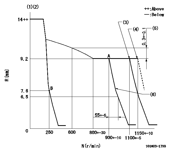
N:Pump speed
R:Rack position (mm)
(1)Target notch: K
(2)The torque control spring must does not have a set force.
(3)Torque spring does not operate.
(4)At shipping
(5)Rack difference between N = N1 and N = N2
(6)Idle sub spring setting: L1.
----------
K=15 N1=900r/min N2=600r/min L1=7.3+-0.1mm
----------
----------
K=15 N1=900r/min N2=600r/min L1=7.3+-0.1mm
----------
Speed control lever angle
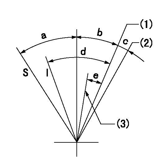
I:Idle
S:Stop
(1)Pump speed = aa
(2)At shipping
(3)Pump speed = bb
----------
aa=1100r/min bb=900r/min
----------
a=32deg+-3deg b=10deg+-5deg c=(2deg) d=25deg+-5deg e=7deg+-5deg
----------
aa=1100r/min bb=900r/min
----------
a=32deg+-3deg b=10deg+-5deg c=(2deg) d=25deg+-5deg e=7deg+-5deg
Stop lever angle

N:Pump normal
S:Stop the pump.
----------
----------
a=19deg+-5deg b=53deg+-5deg
----------
----------
a=19deg+-5deg b=53deg+-5deg
Timing setting

(1)Pump vertical direction
(2)Coupling's key groove position at No 1 cylinder's beginning of injection
(3)-
(4)-
----------
----------
a=(10deg)
----------
----------
a=(10deg)
Information:
Stopping the engine immediately after it has been working under load can result in overheating and accelerated wear of the engine components. Allow the engine to cool down before stopping. Avoiding hot engine shutdowns will maximize turbocharger shaft and bearing life.
Emergency Stopping
Emergency shutoff controls are for EMERGENCY use ONLY. DO NOT use Emergency shutoff devices or controls for normal stopping procedure.
Make sure that any external system components that have been operating to support engine operation are secured after any stop.Emergency Stop Buttons
Emergency Stop Button, shown mounted on a junction box.Emergency stops may be made by pushing the Emergency Stop Button located on the junction box (if equipped). Both the Button and the air inlet shutoff (if equipped) require resetting before the engine will start.
Control Panel Emergency Stop Button.If equipped with the EMCPII Control Panel, press the Emergency Stop Button for an emergency stop. The ECS must be reset before resuming operation. Move the ECS to the OFF/RESET position. The ECS can also be used to shut the engine off in an emergency. Move the ECS to the OFF/RESET position. The engine will immediately shut off.Manual Stopping
A manual shutoff shaft is provided to override the governor control. The shaft will move the fuel control linkage to the FUEL OFF position. Refer to the Model Views for the engine location of the shaft. The engine may be stopped by using the shaft and the Woodward Actuator (if equipped) or the Mechanical Governor (if equipped).
Typical Woodward Actuator Control Lever.If equipped with a Woodward Actuator, move the control lever to the FUEL OFF position.
Typical Mechanical Governor ControlIf equipped with a Mechanical Governor Control, move the control to the FUEL OFF position.Hold the lever at the FUEL OFF position until the engine stops.Air Shutoff (If Equipped)
Some engines are equipped with an air shutoff, located between the aftercooler and the turbocharger. If equipped with an air shutoff lever, move the lever to the OFF position.Manual Stop Procedure
There may be several ways to shut off your engine. Make sure the shutoff procedures are understood. Use the following general guidelines for stopping the engine.EPG Engines
If the ECS is in the AUTO position and the remote contact opens, the engine will run for a pre-programmed cool down period. This will only occur when the cool down mode is used. If the cool down mode is not used, the engine will shut off immediately.
If the ECS is in the AUTO position, the remote contact opens, and the cool down time expires, the CTR will be unlatched and the starting motors may be re-engaged.1. Open the main electrical circuit breaker to remove the load.2. The engine should be run for a cool down period before being shut off. This can be accomplished with the COOLDOWN STOP switch, or the operator can control the cool down and shut off.
To use the COOLDOWN/STOP switch, turn the ECS to the COOLDOWN/STOP position. The engine will operate for a pre-programmed time period. The timer will active the fuel shutoff after the cool down.Alternatively,