Information injection-pump assembly
ZEXEL
101603-1620
1016031620
MITSUBISHI
ME039283
me039283
Rating:
Service parts 101603-1620 INJECTION-PUMP ASSEMBLY:
1.
_
6.
COUPLING PLATE
7.
COUPLING PLATE
8.
_
9.
_
11.
Nozzle and Holder
12.
Open Pre:MPa(Kqf/cm2)
21.6(220)
15.
NOZZLE SET
Cross reference number
ZEXEL
101603-1620
1016031620
MITSUBISHI
ME039283
me039283
Zexel num
Bosch num
Firm num
Name
101603-1620
ME039283 MITSUBISHI
INJECTION-PUMP ASSEMBLY
6D14T * K
6D14T * K
Calibration Data:
Adjustment conditions
Test oil
1404 Test oil ISO4113 or {SAEJ967d}
1404 Test oil ISO4113 or {SAEJ967d}
Test oil temperature
degC
40
40
45
Nozzle and nozzle holder
105780-8140
Bosch type code
EF8511/9A
Nozzle
105780-0000
Bosch type code
DN12SD12T
Nozzle holder
105780-2080
Bosch type code
EF8511/9
Opening pressure
MPa
17.2
Opening pressure
kgf/cm2
175
Injection pipe
Outer diameter - inner diameter - length (mm) mm 6-2-600
Outer diameter - inner diameter - length (mm) mm 6-2-600
Overflow valve opening pressure
kPa
255
221
289
Overflow valve opening pressure
kgf/cm2
2.6
2.25
2.95
Tester oil delivery pressure
kPa
157
157
157
Tester oil delivery pressure
kgf/cm2
1.6
1.6
1.6
Direction of rotation (viewed from drive side)
Left L
Left L
Injection timing adjustment
Direction of rotation (viewed from drive side)
Left L
Left L
Injection order
1-5-3-6-
2-4
Pre-stroke
mm
3
2.95
3.05
Beginning of injection position
Governor side NO.1
Governor side NO.1
Difference between angles 1
Cal 1-5 deg. 60 59.5 60.5
Cal 1-5 deg. 60 59.5 60.5
Difference between angles 2
Cal 1-3 deg. 120 119.5 120.5
Cal 1-3 deg. 120 119.5 120.5
Difference between angles 3
Cal 1-6 deg. 180 179.5 180.5
Cal 1-6 deg. 180 179.5 180.5
Difference between angles 4
Cyl.1-2 deg. 240 239.5 240.5
Cyl.1-2 deg. 240 239.5 240.5
Difference between angles 5
Cal 1-4 deg. 300 299.5 300.5
Cal 1-4 deg. 300 299.5 300.5
Injection quantity adjustment
Adjusting point
-
Rack position
12.5
Pump speed
r/min
850
850
850
Each cylinder's injection qty
mm3/st.
88
85.8
90.2
Basic
*
Fixing the rack
*
Standard for adjustment of the maximum variation between cylinders
*
Injection quantity adjustment_02
Adjusting point
C
Rack position
8.2+-0.5
Pump speed
r/min
275
275
275
Each cylinder's injection qty
mm3/st.
10.5
9
12
Fixing the rack
*
Standard for adjustment of the maximum variation between cylinders
*
Injection quantity adjustment_03
Adjusting point
A
Rack position
R1(12.5)
Pump speed
r/min
850
850
850
Average injection quantity
mm3/st.
88
87
89
Fixing the lever
*
Boost pressure
kPa
58.7
58.7
Boost pressure
mmHg
440
440
Injection quantity adjustment_04
Adjusting point
D
Rack position
11.5
Pump speed
r/min
600
600
600
Average injection quantity
mm3/st.
67
65
69
Fixing the lever
*
Boost pressure
kPa
0
0
0
Boost pressure
mmHg
0
0
0
Injection quantity adjustment_05
Adjusting point
E
Rack position
-
Pump speed
r/min
100
100
100
Average injection quantity
mm3/st.
90
70
110
Fixing the lever
*
Boost pressure
kPa
0
0
0
Boost pressure
mmHg
0
0
0
Boost compensator adjustment
Pump speed
r/min
650
650
650
Rack position
11.5
Boost pressure
kPa
22.7
21.4
24
Boost pressure
mmHg
170
160
180
Boost compensator adjustment_02
Pump speed
r/min
650
650
650
Rack position
12.5
Boost pressure
kPa
45.3
38.6
52
Boost pressure
mmHg
340
290
390
Timer adjustment
Pump speed
r/min
1190--
Advance angle
deg.
0
0
0
Remarks
Start
Start
Timer adjustment_02
Pump speed
r/min
1140
Advance angle
deg.
0.5
Timer adjustment_03
Pump speed
r/min
1300
Advance angle
deg.
2
1.5
2.5
Timer adjustment_04
Pump speed
r/min
1400
Advance angle
deg.
3.5
3
4
Remarks
Finish
Finish
Test data Ex:
Governor adjustment
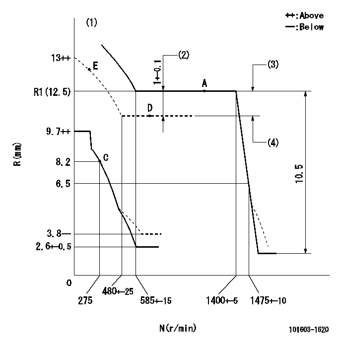
N:Pump speed
R:Rack position (mm)
(1)Beginning of damper spring operation: DL
(2)Boost compensator stroke
(3)Boost pressure: not less than BP1
(4)Boost pressure: not less than BP2
----------
DL=6-0.2mm BP1=58.7kPa(440mmHg) BP2=0kPa(0mmHg)
----------
----------
DL=6-0.2mm BP1=58.7kPa(440mmHg) BP2=0kPa(0mmHg)
----------
Speed control lever angle

F:Full speed
----------
----------
a=9.5deg+-5deg
----------
----------
a=9.5deg+-5deg
0000000901
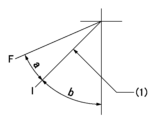
F:Full load
I:Idle
(1)Stopper bolt setting
----------
----------
a=35deg+-3deg b=50.5deg+-5deg
----------
----------
a=35deg+-3deg b=50.5deg+-5deg
Stop lever angle
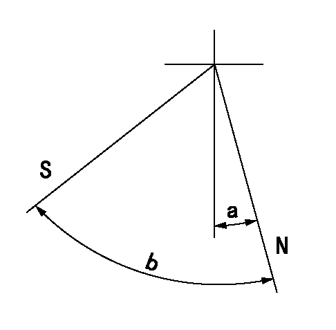
N:Pump normal
S:Stop the pump.
----------
----------
a=0deg+-5deg b=41.5deg+-5deg
----------
----------
a=0deg+-5deg b=41.5deg+-5deg
Timing setting

(1)Pump vertical direction
(2)Position of timer's tooth at No 1 cylinder's beginning of injection
(3)B.T.D.C.: aa
(4)-
----------
aa=14deg
----------
a=(2deg)
----------
aa=14deg
----------
a=(2deg)
Information:
The regulator valve is mounted at the lower portion of the injection pump on the left side of the crankcase. It regulates pressure of engine oil that flows through the oil filter and oil cooler into the main gallery.When oil pressure in the main gallery exceeds specified level the regulator valve opens to return part of engine oil to the oil pan.(5) Lubrication of All PartsThe engine oil routed to the main oil gallery lubricates all parts as described in the following.(a) Main bearing and connecting rod bearing The oil main gallery connects to the crankshaft main bearing through oil holes for lubrication of the main bearing. Part of engine oil that has lubricated the main bearing flows through the oil
Have questions with 101603-1620?
Group cross 101603-1620 ZEXEL
Mitsubishi
101603-1620
ME039283
INJECTION-PUMP ASSEMBLY
6D14T
6D14T