Information injection-pump assembly
ZEXEL
101603-1192
1016031192
M.BISHI-HI.-NAG
EZ40087
ez40087
Rating:
Service parts 101603-1192 INJECTION-PUMP ASSEMBLY:
1.
_
6.
COUPLING PLATE
7.
COUPLING PLATE
8.
_
9.
_
11.
Nozzle and Holder
12.
Open Pre:MPa(Kqf/cm2)
21.6(220)
15.
NOZZLE SET
Cross reference number
ZEXEL
101603-1192
1016031192
M.BISHI-HI.-NAG
EZ40087
ez40087
Zexel num
Bosch num
Firm num
Name
101603-1192
EZ40087 M.BISHI-HI.-NAG
INJECTION-PUMP ASSEMBLY
6A1 * K
6A1 * K
Calibration Data:
Adjustment conditions
Test oil
1404 Test oil ISO4113 or {SAEJ967d}
1404 Test oil ISO4113 or {SAEJ967d}
Test oil temperature
degC
40
40
45
Nozzle and nozzle holder
105780-8140
Bosch type code
EF8511/9A
Nozzle
105780-0000
Bosch type code
DN12SD12T
Nozzle holder
105780-2080
Bosch type code
EF8511/9
Opening pressure
MPa
17.2
Opening pressure
kgf/cm2
175
Injection pipe
Outer diameter - inner diameter - length (mm) mm 6-2-600
Outer diameter - inner diameter - length (mm) mm 6-2-600
Overflow valve
131424-3720
Overflow valve opening pressure
kPa
255
221
289
Overflow valve opening pressure
kgf/cm2
2.6
2.25
2.95
Tester oil delivery pressure
kPa
157
157
157
Tester oil delivery pressure
kgf/cm2
1.6
1.6
1.6
Direction of rotation (viewed from drive side)
Left L
Left L
Injection timing adjustment
Direction of rotation (viewed from drive side)
Left L
Left L
Injection order
1-5-3-6-
2-4
Pre-stroke
mm
4.2
4.15
4.25
Beginning of injection position
Governor side NO.1
Governor side NO.1
Difference between angles 1
Cal 1-5 deg. 60 59.5 60.5
Cal 1-5 deg. 60 59.5 60.5
Difference between angles 2
Cal 1-3 deg. 120 119.5 120.5
Cal 1-3 deg. 120 119.5 120.5
Difference between angles 3
Cal 1-6 deg. 180 179.5 180.5
Cal 1-6 deg. 180 179.5 180.5
Difference between angles 4
Cyl.1-2 deg. 240 239.5 240.5
Cyl.1-2 deg. 240 239.5 240.5
Difference between angles 5
Cal 1-4 deg. 300 299.5 300.5
Cal 1-4 deg. 300 299.5 300.5
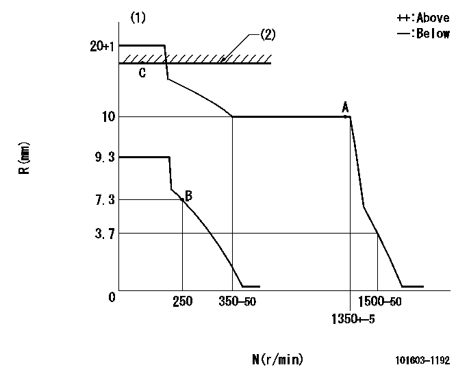
Injection quantity adjustment
Adjusting point
A
Rack position
10
Pump speed
r/min
1300
1300
1300
Average injection quantity
mm3/st.
74.2
72.7
75.7
Max. variation between cylinders
%
0
-2.5
2.5
Basic
*
Fixing the lever
*
Injection quantity adjustment_02
Adjusting point
B
Rack position
7.5+-0.5
Pump speed
r/min
250
250
250
Average injection quantity
mm3/st.
10
8.5
11.5
Max. variation between cylinders
%
0
-15
15
Fixing the rack
*
Remarks
Adjust only variation between cylinders; adjust governor according to governor specifications.
Adjust only variation between cylinders; adjust governor according to governor specifications.
Injection quantity adjustment_03
Adjusting point
C
Rack position
16.9+-0.
5
Pump speed
r/min
100
100
100
Average injection quantity
mm3/st.
147
147
157
Fixing the lever
*
Rack limit
*
Timer adjustment
Pump speed
r/min
700
Advance angle
deg.
0.5
Timer adjustment_02
Pump speed
r/min
1000
Advance angle
deg.
2.2
1.7
2.7
Timer adjustment_03
Pump speed
r/min
1200
Advance angle
deg.
5
4.5
5.5
Remarks
Finish
Finish
Test data Ex:
Governor adjustment
N:Pump speed
R:Rack position (mm)
(1)Target notch: K
(2)RACK LIMIT
----------
K=15
----------
----------
K=15
----------
Speed control lever angle
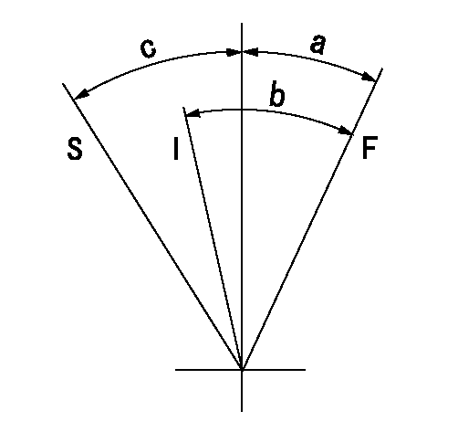
F:Full speed
I:Idle
S:Stop
----------
----------
a=24deg+-5deg b=32.5deg+-5deg c=32deg+-3deg
----------
----------
a=24deg+-5deg b=32.5deg+-5deg c=32deg+-3deg
Stop lever angle

N:Pump normal
S:Stop the pump.
----------
----------
a=43deg+-5deg b=53deg+-5deg
----------
----------
a=43deg+-5deg b=53deg+-5deg
Timing setting

(1)Pump vertical direction
(2)Position of gear mark '2' at No 1 cylinder's beginning of injection
(3)B.T.D.C.: aa
(4)-
----------
aa=19deg
----------
a=(90deg)
----------
aa=19deg
----------
a=(90deg)
Information:
Proper operation and maintenance are key factors in obtaining the maximum life and economy of the engine. Following the directions in this manual will lower operating costs.The time needed for the engine to reach the normal mode of operation is usually less than the time taken for a walk-around-inspection of the engine.After the engine is started and the cold low idle operation is completed, the engine can be operated at rated speed and low power. The engine will reach normal operating temperature faster when operated at rated speed and low power demand than when idled at no load. Typically the engine should be up to operating temperature in a few minutes.Governors and Actuators
Your engine may be equipped with a:* full-range governor* Woodward PSG Governor* Woodward 1724 Actuator* Woodward 524 Actuator
PSG Actuator
1724/524 ActuatorWoodward Governors/Actuators are usually electrically operated from a control panel. The application is usually an EPG power generator set. On standby gen sets the governor may be set to operate only at Full Load Speed.Change Engine Speed
If equipped with a control panel, a RAISE/LOWER switch or a speed setting potentiometer is used to adjust the operating speed.Starting, Operating and Stopping Engines Equipped with Control Panels
For all information regarding the generator control panel used for starting, operating and stopping the engine, refer to the Engine Protection Devices Generator Set Control Panel topic in this publication or Caterpillar SR4 Generators and Control Panels, SEBU6150. Additional information and programming instructions are provided in the Service Manual for your specific control panel.Mechanical Governors (If Equipped)
Governor Control LeverYour engine may be equipped with a full-range governor. Most other manufacturers' engines have min-max type governors that only govern at high and low idle to prevent the engine from overspeeding or dying. With the min-max governor, the position of the speed lever determines the amount of fuel delivered to the engine.With the full-range governor, the position of the speed lever sets engine speed and helps hold a constant speed independent of load which makes operation easier.The governor control motor is a 24 volt motor which allows for engine speed control from a remote location through a governor RAISE/LOWER switch. This governor control switch is used with the optional EMCP II. Always increase engine speed to high idle before applying load.For information regarding initial checks and adjustments, refer to the Service Manual or contact your Caterpillar dealer.Driven Equipment Without Load
1. Move the governor control lever to half engine speed.2. Interrupted starts put excessive stress on the drive train and waste fuel. To get the driven equipment in motion, engage the clutch smoothly, with no load on the equipment. This should result in a smooth, easy start without increasing the engine speed above low idle or slipping the clutch. For generator sets, move the governor control to high idle (full load) position (1800 rpm for 60 Hz and 1500 rpm for 50 Hz).3. Apply the load and check the gauges and equipment for proper operation. Begin operating the engine at low load. After normal oil pressure
Have questions with 101603-1192?
Group cross 101603-1192 ZEXEL
Mitsubishi
M.Bishi-Hi.-Nag
101603-1192
EZ40087
INJECTION-PUMP ASSEMBLY
6A1
6A1