Information injection-pump assembly
ZEXEL
101603-0930
1016030930
ISUZU
1156018040
1156018040

Rating:
Cross reference number
ZEXEL
101603-0930
1016030930
ISUZU
1156018040
1156018040
Zexel num
Bosch num
Firm num
Name
Calibration Data:
Adjustment conditions
Test oil
1404 Test oil ISO4113 or {SAEJ967d}
1404 Test oil ISO4113 or {SAEJ967d}
Test oil temperature
degC
40
40
45
Nozzle and nozzle holder
105780-8140
Bosch type code
EF8511/9A
Nozzle
105780-0000
Bosch type code
DN12SD12T
Nozzle holder
105780-2080
Bosch type code
EF8511/9
Opening pressure
MPa
17.2
Opening pressure
kgf/cm2
175
Injection pipe
Outer diameter - inner diameter - length (mm) mm 6-2-600
Outer diameter - inner diameter - length (mm) mm 6-2-600
Overflow valve
131424-0220
Overflow valve opening pressure
kPa
147
113
181
Overflow valve opening pressure
kgf/cm2
1.5
1.15
1.85
Tester oil delivery pressure
kPa
157
157
157
Tester oil delivery pressure
kgf/cm2
1.6
1.6
1.6
Direction of rotation (viewed from drive side)
Right R
Right R
Injection timing adjustment
Direction of rotation (viewed from drive side)
Right R
Right R
Injection order
1-4-2-6-
3-5
Pre-stroke
mm
3.7
3.65
3.75
Beginning of injection position
Drive side NO.1
Drive side NO.1
Difference between angles 1
Cal 1-4 deg. 60 59.5 60.5
Cal 1-4 deg. 60 59.5 60.5
Difference between angles 2
Cyl.1-2 deg. 120 119.5 120.5
Cyl.1-2 deg. 120 119.5 120.5
Difference between angles 3
Cal 1-6 deg. 180 179.5 180.5
Cal 1-6 deg. 180 179.5 180.5
Difference between angles 4
Cal 1-3 deg. 240 239.5 240.5
Cal 1-3 deg. 240 239.5 240.5
Difference between angles 5
Cal 1-5 deg. 300 299.5 300.5
Cal 1-5 deg. 300 299.5 300.5
Injection quantity adjustment
Adjusting point
A
Rack position
10.9
Pump speed
r/min
1150
1150
1150
Average injection quantity
mm3/st.
106.2
104.2
108.2
Max. variation between cylinders
%
0
-4
4
Fixing the lever
*
Injection quantity adjustment_02
Adjusting point
B
Rack position
11.2
Pump speed
r/min
700
700
700
Average injection quantity
mm3/st.
108.1
107.1
109.1
Max. variation between cylinders
%
0
-2
2
Basic
*
Fixing the lever
*
Injection quantity adjustment_03
Adjusting point
C
Rack position
8.6+-0.5
Pump speed
r/min
225
225
225
Average injection quantity
mm3/st.
11.5
9.2
13.8
Max. variation between cylinders
%
0
-13
13
Fixing the rack
*
Injection quantity adjustment_04
Adjusting point
D
Rack position
-
Pump speed
r/min
150
150
150
Each cylinder's injection qty
mm3/st.
140
140
Fixing the lever
*
Remarks
After startup boost setting
After startup boost setting
Injection quantity adjustment_05
Adjusting point
E
Rack position
9.8
Pump speed
r/min
700
700
700
Average injection quantity
mm3/st.
73
71
75
Max. variation between cylinders
%
0
-2
2
Fixing the lever
*
Remarks
At absolute pressure 61.3 kPa {460 mmHg}
At absolute pressure 61.3 kPa {460 mmHg}
Timer adjustment
Pump speed
r/min
500
Advance angle
deg.
0.3
Timer adjustment_02
Pump speed
r/min
600
Advance angle
deg.
0.8
0.1
0.8
Timer adjustment_03
Pump speed
r/min
700
Advance angle
deg.
0.8
0.3
1.3
Timer adjustment_04
Pump speed
r/min
900
Advance angle
deg.
2
1.5
2.5
Timer adjustment_05
Pump speed
r/min
1150
Advance angle
deg.
4
3.5
4.5
Remarks
Finish
Finish
Test data Ex:
Governor adjustment
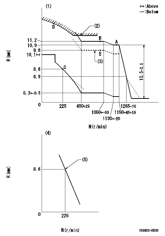
N:Pump speed
R:Rack position (mm)
(1)Damper spring setting: DL
(2)Excess fuel setting for starting: SXL
(3)Aneroid compensator absolute pressure: P1
(4)Variable speed specification: idling adjustment
(5)Main spring setting
----------
DL=6.5+-0.5mm SXL=12.1+-0.1mm P1=460+-5mmHg
----------
----------
DL=6.5+-0.5mm SXL=12.1+-0.1mm P1=460+-5mmHg
----------
Speed control lever angle

F:Full speed
I:Idle
(1)Stopper bolt setting
----------
----------
a=(14deg)+-5deg b=3deg+-5deg
----------
----------
a=(14deg)+-5deg b=3deg+-5deg
0000000901
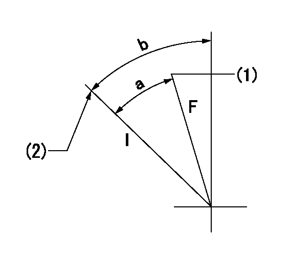
F:Full load
I:Idle
(1)Attach the return spring to the upper hole and adjust.
(2)Stopper bolt setting
----------
----------
a=21deg+-3deg b=30deg+-5deg
----------
----------
a=21deg+-3deg b=30deg+-5deg
Stop lever angle

N:Pump normal
S:Stop the pump.
----------
----------
a=65.5deg+-5deg b=71deg+-5deg
----------
----------
a=65.5deg+-5deg b=71deg+-5deg
0000001501 ACS
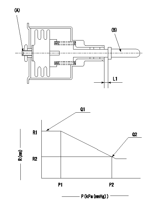
(A) Set screw
(B) Push rod 1
1. Aneroid compensator unit adjustment
(1)Screw in (A) to obtain L1.
2. Adjustment following governor installation
(1)Set the speed of the pump to N1 r/min and fix the control lever at the full set position.
(2)Screw in the aneroid compensator to obtain the performance shown in the graph above.
----------
N1=700r/min L1=(0.1~0.5)mm
----------
R1=11.2mm R2=9.8mm P1=(90.6)kPa((680)mmHg) P2=61.3+-0.7kPa(460+-5mmHg) Q1=108.1+-1cm3/1000st Q2=(73)+-1cm3/1000st
----------
N1=700r/min L1=(0.1~0.5)mm
----------
R1=11.2mm R2=9.8mm P1=(90.6)kPa((680)mmHg) P2=61.3+-0.7kPa(460+-5mmHg) Q1=108.1+-1cm3/1000st Q2=(73)+-1cm3/1000st
Timing setting

(1)Pump vertical direction
(2)Position of timer's threaded hole at No 1 cylinder's beginning of injection
(3)B.T.D.C.: aa
(4)-
----------
aa=17deg
----------
a=(60deg)
----------
aa=17deg
----------
a=(60deg)
Information:
Cold Weather Battery Maintenance
General Maintenance
1. After adding make-up water, charge the battery. The added water could dilute the electrolyte enough without charging to cause freezing and permanent damage to the battery.2. Keep the batteries fully charged either by operating the charging system or by using a battery charger.3. Keep the battery warm when not in use. In an unheated area, the heat from a lighted electric bulb is usually sufficient.
Use only a shop cord with a heavy wire guard around the light bulb.
Do not lay a lighted bulb directly on a battery case; the heat at point of contact could melt the battery case.Do not lay cloth or flammable material in contact with a lighted bulb; charring and/or fire could result.4. Use starting aids as instructed for starting the engine.5. Use booster batteries as required. Connect the batteries as instructed below.6. If a battery is not going to be used for a period of time, be sure the battery is fully charged while stored. Use a battery hydrometer to check the specific gravity of each cell, and use a battery charger to keep the battery charged. See the instructions below.Voltage Test (After Load)
A load test should be made on a battery that discharges very rapidly when in use. To do this apply a resistance of three times the ampere/hour rating of the battery across the battery main terminals. Allow the resistance to discharge the the battery for 15 seconds and immediately test the battery voltage. A 6 volt battery in good condition will test 4.5 volts; a 12 volt battery in good condition will test 9 volts and a 24 volt battery will test 18 volts.Starter
No periodic service is indicated for the electric starter brushes between general reconditioning periods. The brushes should only be inspected after removal of the starter from the engine and removal of the commutator end bearing frame. The electric starter commutator end and drive end bearings are equipped with wicks for lubrication purposes. The wicks should be saturated with oil whenever the electric starter is removed or disassembled.It is suggested that cleaning and reconditioning be entrusted to your authorized dealer.Pinion Clearance Adjustment
Whenever the solenoid is installed, the pinion clearance should be adjusted. The adjustment should be made with the starting motor removed.Bench test and adjust the pinion clearance at installation of solenoid as follows:
CIRCUIT FOR CHECKING AND ADJUSTING PINION CLEARANCE1. Install the solenoid without connector from the MOTOR terminal on solenoid to the motor.2. Connect a battery, of the same voltage as the solenoid, to the terminal marked SW.3. Connect the other side of battery to ground terminal or to solenoid frame.
ADJUSTING PINION CLEARANCE4. MOMENTARILY flash a jumper wire from the solenoid terminal marked MOTOR to the frame or ground terminal. The pinion will shift into cranking position and will remain there until the battery is disconnected.5. Push pinion towards commutator end to eliminate free movement.6. Pinion clearance should be .36 in. (9.14 mm).7. Adjust clearance by removing plug and turning shaft nut.
ADJUSTING PINION