Information injection-pump assembly
ZEXEL
101603-0910
1016030910
ISUZU
1156019600
1156019600
Rating:
Service parts 101603-0910 INJECTION-PUMP ASSEMBLY:
1.
_
7.
COUPLING PLATE
8.
_
9.
_
11.
Nozzle and Holder
12.
Open Pre:MPa(Kqf/cm2)
19.6(200)
15.
NOZZLE SET
Cross reference number
ZEXEL
101603-0910
1016030910
ISUZU
1156019600
1156019600
Zexel num
Bosch num
Firm num
Name
Calibration Data:
Adjustment conditions
Test oil
1404 Test oil ISO4113 or {SAEJ967d}
1404 Test oil ISO4113 or {SAEJ967d}
Test oil temperature
degC
40
40
45
Nozzle and nozzle holder
105780-8140
Bosch type code
EF8511/9A
Nozzle
105780-0000
Bosch type code
DN12SD12T
Nozzle holder
105780-2080
Bosch type code
EF8511/9
Opening pressure
MPa
17.2
Opening pressure
kgf/cm2
175
Injection pipe
Outer diameter - inner diameter - length (mm) mm 6-2-600
Outer diameter - inner diameter - length (mm) mm 6-2-600
Overflow valve
132424-0620
Overflow valve opening pressure
kPa
157
123
191
Overflow valve opening pressure
kgf/cm2
1.6
1.25
1.95
Tester oil delivery pressure
kPa
157
157
157
Tester oil delivery pressure
kgf/cm2
1.6
1.6
1.6
Direction of rotation (viewed from drive side)
Left L
Left L
Injection timing adjustment
Direction of rotation (viewed from drive side)
Left L
Left L
Injection order
1-5-3-6-
2-4
Pre-stroke
mm
3.7
3.65
3.75
Beginning of injection position
Governor side NO.1
Governor side NO.1
Difference between angles 1
Cal 1-5 deg. 60 59.5 60.5
Cal 1-5 deg. 60 59.5 60.5
Difference between angles 2
Cal 1-3 deg. 120 119.5 120.5
Cal 1-3 deg. 120 119.5 120.5
Difference between angles 3
Cal 1-6 deg. 180 179.5 180.5
Cal 1-6 deg. 180 179.5 180.5
Difference between angles 4
Cyl.1-2 deg. 240 239.5 240.5
Cyl.1-2 deg. 240 239.5 240.5
Difference between angles 5
Cal 1-4 deg. 300 299.5 300.5
Cal 1-4 deg. 300 299.5 300.5
Injection quantity adjustment
Adjusting point
-
Rack position
12.6
Pump speed
r/min
850
850
850
Average injection quantity
mm3/st.
116.3
114.7
117.9
Max. variation between cylinders
%
0
-2.5
2.5
Basic
*
Fixing the rack
*
Standard for adjustment of the maximum variation between cylinders
*
Injection quantity adjustment_02
Adjusting point
H
Rack position
9.5+-0.5
Pump speed
r/min
280
280
280
Average injection quantity
mm3/st.
9.4
7.4
11.4
Max. variation between cylinders
%
0
-14
14
Fixing the rack
*
Standard for adjustment of the maximum variation between cylinders
*
Injection quantity adjustment_03
Adjusting point
A
Rack position
R1(12.6)
Pump speed
r/min
850
850
850
Average injection quantity
mm3/st.
116.3
114.7
117.9
Basic
*
Fixing the lever
*
Remarks
After setting aneroid compensatory.
After setting aneroid compensatory.
Injection quantity adjustment_04
Adjusting point
B
Rack position
R1-0.3
Pump speed
r/min
1250
1250
1250
Average injection quantity
mm3/st.
112.8
109.6
116
Fixing the lever
*
Injection quantity adjustment_05
Adjusting point
I
Rack position
R2(14.2)
Pump speed
r/min
100
100
100
Average injection quantity
mm3/st.
102.5
102.5
112.5
Fixing the lever
*
Rack limit
*
Timer adjustment
Pump speed
r/min
950--
Advance angle
deg.
0
0
0
Remarks
Start
Start
Timer adjustment_02
Pump speed
r/min
900
Advance angle
deg.
0.5
Timer adjustment_03
Pump speed
r/min
1250
Advance angle
deg.
2
1.5
2.5
Remarks
Finish
Finish
Test data Ex:
Governor adjustment
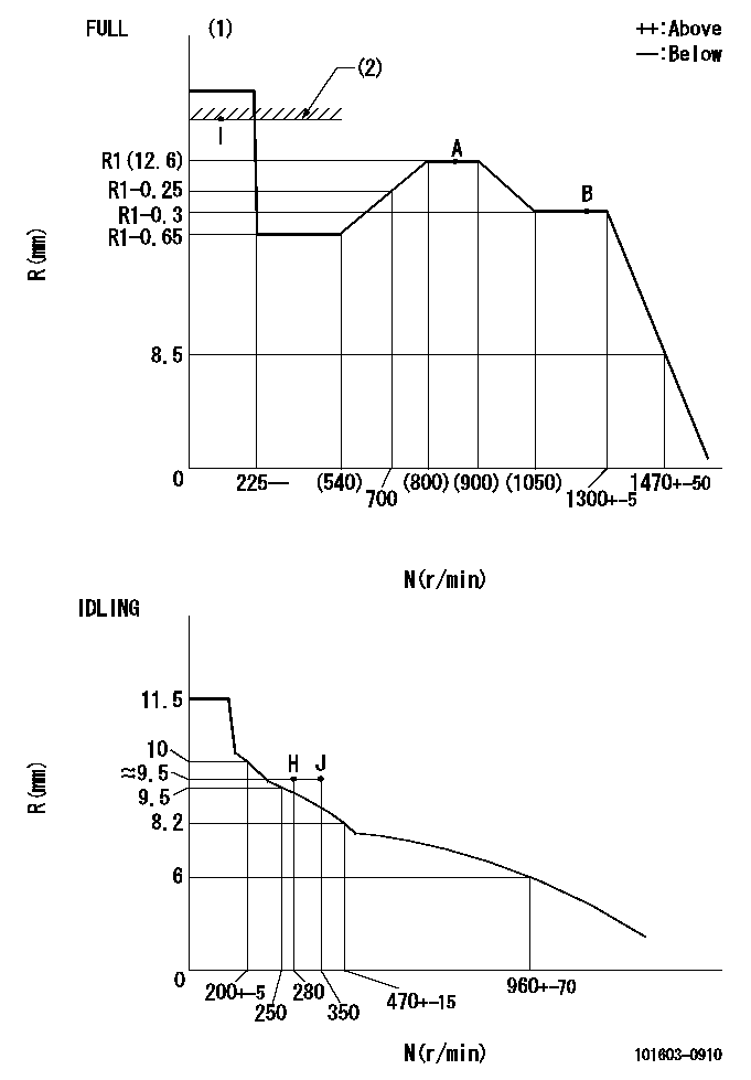
N:Pump speed
R:Rack position (mm)
(1)Torque cam stamping: T1
(2)RACK LIMIT
----------
T1=B40
----------
----------
T1=B40
----------
Speed control lever angle

F:Full speed
I:Idle
(1)Stopper bolt setting
----------
----------
a=19deg+-5deg b=28deg+-3deg
----------
----------
a=19deg+-5deg b=28deg+-3deg
Stop lever angle
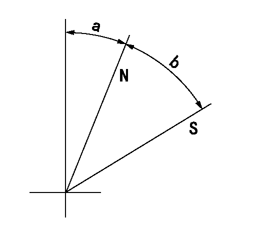
N:Pump normal
S:Stop the pump.
----------
----------
a=25deg+-5deg b=40deg+-5deg
----------
----------
a=25deg+-5deg b=40deg+-5deg
0000001501 ACS
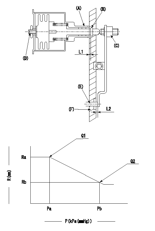
(A) Housing
(B) Snap ring
(C) adjusting screw
(D) Set screw
(E): Push rod
(F) Spacer
1. Adjustment of the aneroid compensator
(1)Adjust with the (D) set screw so that the clearance between the (A) housing and (B) snap ring is L1.
(2)Select the push rod (E) so that the distance from the end surface of the (F) spacer becomes L2.
(3)(C) Turn the screw to adjust the beginning of aneroid compensator operation.
2. Adjustment when mounting the governor.
(1)Set the speed of the pump to N1 r/min and fix the control lever at the full set position.
(2)Adjust using screw C to obtain the performance shown in the graph above.
(3)After final adjustment, confirm that the gap between housing (A) and snapring (B) is L3.
----------
N1=850r/min L1=1.4~1.7mm L2=0.5+-0.5mm L3=0.1~0.5mm
----------
Ra=R1(12.6)mm Rb=R3(12)mm Pa=4+-2.7kPa(30+-20mmHg) Pb=36kPa(270mmHg) Q1=116.3+-1mm3/st Q2=103.6+-1.6mm3/st
----------
N1=850r/min L1=1.4~1.7mm L2=0.5+-0.5mm L3=0.1~0.5mm
----------
Ra=R1(12.6)mm Rb=R3(12)mm Pa=4+-2.7kPa(30+-20mmHg) Pb=36kPa(270mmHg) Q1=116.3+-1mm3/st Q2=103.6+-1.6mm3/st
Timing setting

(1)Pump vertical direction
(2)Position of timer's threaded hole at No 1 cylinder's beginning of injection
(3)B.T.D.C.: aa
(4)-
----------
aa=15deg
----------
a=(40deg)
----------
aa=15deg
----------
a=(40deg)
Information:
Final Fuel Filter
The filter element collects and holds contaminants and cannot be washed or otherwise restored.To remove the used filter, proceed as follows:1. Stop the engine and close the diesel fuel line valve (if equipped).2. Unscrew and remove filter. 3. Clean the gasket sealing surfaces on the filter bases. 4. Lubricate the new filter gasket with clean diesel fuel.
Do not pour fuel into the new filter element before installing. Prime the system as instructed in the topic, PRIMING THE FUEL SYSTEM.
5. Tighten the filter by hand until the gasket contacts the base, then tighten 1/2 to 3/4 turn more.6. Start the engine and run at 1000 rpm for several minutes and check for leaks. If the engine fails to start, prime the fuel system. See the topic TO PRIME THE SYSTEM. Keep New Fuel Filters On Hand
Extra filters should be kept on hand for replacement. Always keep filters wrapped in their original carton to insure against dust and dirt accumulation which will shorten the life of the filters or may cause damage to the fuel injection equipment.To Prime The System
If air is trapped in the fuel system, the diesel engine will either not start, or will misfire. Then it is necessary to prime the system.The fuel priming pump is mounted on the fuel filter base. If the fuel filter is changed or if the engine has run out of fuel, prime the fuel system as follows: 1. Be sure the fuel line valve is open and the engine shutoff control is off.2. Unlock the fuel priming pump.3. Operate priming pump until increased resistance is felt.4. Lock fuel priming pump.If the engine fails to start or continues to misfire or smoke, further bleeding is necessary. With engine running, or with the use of the priming pump, loosen fuel line nuts, one at a time, several times in succession and allow fuel to run until free of air bubbles. Tighten fuel line nuts.
LOOSENING FUEL INJECTION LINE TO BLEED SYSTEMFuel Injection Equipment
When improper fuel injection is affecting engine operation, a systematic check should be made to determine the cause. The most likely cause is dirt or water in the fuel. Drain the sediment from the fuel tank. Check the fuel pressure gauge as mentioned in the topic, FUEL FILTERING SYSTEM. Replace the filters if necessary. Then prime the fuel system until clean fuel reaches the fuel injection pumps. If the fuel system is air bound, priming the system will overcome the difficulty.If the engine is running irregularly, smoking, or knocking, a fuel injection valve may not be spraying the fuel properly.Direct Injection System
The fuel system of direct injection engines is essentially the same as precombustion chamber engines. The absence of the precombustion chamber requires a different fuel nozzle and adapter. Externally the direct injection fuel nozzle resembles the precombustion chamber nozzle except it is longer in length. Nozzle testing and replacement procedure is the same as illustrated for the precombustion chamber engines, except that an extracting tool is used to remove