Information injection-pump assembly
ZEXEL
101603-0783
1016030783
ISUZU
1156018583
1156018583
Rating:
Service parts 101603-0783 INJECTION-PUMP ASSEMBLY:
1.
_
7.
COUPLING PLATE
8.
_
9.
_
11.
Nozzle and Holder
1-15300-104-2
12.
Open Pre:MPa(Kqf/cm2)
18.1{185}

15.
NOZZLE SET
Cross reference number
ZEXEL
101603-0783
1016030783
ISUZU
1156018583
1156018583
Zexel num
Bosch num
Firm num
Name
101603-0783
1156018583 ISUZU
INJECTION-PUMP ASSEMBLY
6BG1 * K 14BF PE6AD PE
6BG1 * K 14BF PE6AD PE
Calibration Data:
Adjustment conditions
Test oil
1404 Test oil ISO4113 or {SAEJ967d}
1404 Test oil ISO4113 or {SAEJ967d}
Test oil temperature
degC
40
40
45
Nozzle and nozzle holder
105780-8140
Bosch type code
EF8511/9A
Nozzle
105780-0000
Bosch type code
DN12SD12T
Nozzle holder
105780-2080
Bosch type code
EF8511/9
Opening pressure
MPa
17.2
Opening pressure
kgf/cm2
175
Injection pipe
Outer diameter - inner diameter - length (mm) mm 6-2-600
Outer diameter - inner diameter - length (mm) mm 6-2-600
Overflow valve
131424-4920
Overflow valve opening pressure
kPa
127
107
147
Overflow valve opening pressure
kgf/cm2
1.3
1.1
1.5
Tester oil delivery pressure
kPa
157
157
157
Tester oil delivery pressure
kgf/cm2
1.6
1.6
1.6
Direction of rotation (viewed from drive side)
Right R
Right R
Injection timing adjustment
Direction of rotation (viewed from drive side)
Right R
Right R
Injection order
1-5-3-6-
2-4
Pre-stroke
mm
3.6
3.55
3.65
Beginning of injection position
Drive side NO.1
Drive side NO.1
Difference between angles 1
Cal 1-5 deg. 60 59.5 60.5
Cal 1-5 deg. 60 59.5 60.5
Difference between angles 2
Cal 1-3 deg. 120 119.5 120.5
Cal 1-3 deg. 120 119.5 120.5
Difference between angles 3
Cal 1-6 deg. 180 179.5 180.5
Cal 1-6 deg. 180 179.5 180.5
Difference between angles 4
Cyl.1-2 deg. 240 239.5 240.5
Cyl.1-2 deg. 240 239.5 240.5
Difference between angles 5
Cal 1-4 deg. 300 299.5 300.5
Cal 1-4 deg. 300 299.5 300.5
Injection quantity adjustment
Adjusting point
-
Rack position
11.5
Pump speed
r/min
900
900
900
Average injection quantity
mm3/st.
73.1
71.5
74.7
Max. variation between cylinders
%
0
-2.5
2.5
Basic
*
Fixing the rack
*
Standard for adjustment of the maximum variation between cylinders
*
Injection quantity adjustment_02
Adjusting point
H
Rack position
9.5+-0.5
Pump speed
r/min
275
275
275
Average injection quantity
mm3/st.
8
6.7
9.3
Max. variation between cylinders
%
0
-14
14
Fixing the rack
*
Standard for adjustment of the maximum variation between cylinders
*
Injection quantity adjustment_03
Adjusting point
A
Rack position
R1(11.5)
Pump speed
r/min
900
900
900
Average injection quantity
mm3/st.
73.1
72.1
74.1
Basic
*
Fixing the lever
*
Injection quantity adjustment_04
Adjusting point
I
Rack position
14+-0.5
Pump speed
r/min
150
150
150
Average injection quantity
mm3/st.
90
90
98
Fixing the lever
*
Rack limit
*
Timer adjustment
Pump speed
r/min
1350--
Advance angle
deg.
0
0
0
Remarks
Start
Start
Timer adjustment_02
Pump speed
r/min
1300
Advance angle
deg.
0.5
Timer adjustment_03
Pump speed
r/min
1400
Advance angle
deg.
2
1.5
2.5
Timer adjustment_04
Pump speed
r/min
1500
Advance angle
deg.
4.5
4
5
Remarks
Finish
Finish
Test data Ex:
Governor adjustment
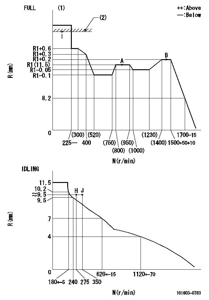
N:Pump speed
R:Rack position (mm)
(1)Torque cam stamping: T1
(2)RACK LIMIT
----------
T1=D27
----------
----------
T1=D27
----------
Speed control lever angle

F:Full speed
I:Idle
(1)Use the hole at R = aa
(2)Stopper bolt set position 'H'
----------
aa=35mm
----------
a=42deg+-5deg b=35deg+-3deg
----------
aa=35mm
----------
a=42deg+-5deg b=35deg+-3deg
Stop lever angle
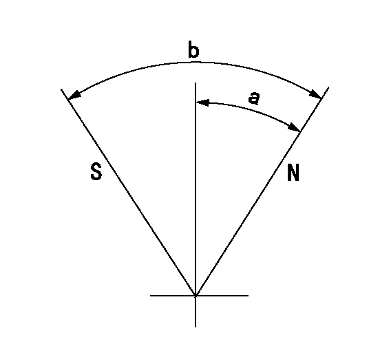
N:Pump normal
S:Stop the pump.
----------
----------
a=25deg+-5deg b=40deg+-5deg
----------
----------
a=25deg+-5deg b=40deg+-5deg
Timing setting

(1)Pump vertical direction
(2)Position of timer's threaded hole at No 1 cylinder's beginning of injection
(3)B.T.D.C.: aa
(4)-
----------
aa=13deg
----------
a=(60deg)
----------
aa=13deg
----------
a=(60deg)
Information:
(1) Bore in idler gear bearing ... 28.600 0.061 mm (1.1260 .0024 in) Diameter of idler gear shaft ... 28.512 0.013 mm (1.1225 .0005 in)Clearance between bearing and shaft ... .014 to .162 mm (.0011 to .0059 in)(2) Clearance between gear and body of pump ... 0.05 to 0.66 mm (.002 to .026 in)(3) Diameter of shafts for pump ... 22.217 0.005 mm (.8747 .0002 in) Bore in bearings for shafts ... 22.286 0.051 mm (.8774 .0020 in)Clearance between shafts and bearings ... .013 to .125 mm (.0010 to .0050 in)(4) Depth that bearings are installed in pump bodies ... 1.52 0.25 mm (.060 .010 in)(5) Length of gears ... 50.808 0.025 mm (2.0003 0.0010 in) Depth of bore in pump body for gears ... 50.935 0.020 mm (2.0053 0.0008 in)Clearance between end of gears and pump body ... 0.081 to 0.173 mm (.0032 to .0068 in)(6) Length of gears ... 38.070 0.025 mm (1.4988 0.0010 in) Depth of bore in pump body for gears ... 38.197 0.020 mm (1.5038 0.0008 in)Clearance between end of gears and pump body ... 0.081 to 0.173 mm (.0032 to .0068 in)(7) Distance from the end of the idler shafts to gear faces ... 21.03 0.13 mm (.828 .005 in) Maximum temperature of gear when shrinking in place ... 400°C (750°F)(8) Distance from the end of the drive shaft to gear face ... 38.23 0.13 mm (1.505 0.005 in) Maximum temperature of gear when shrinking in place ... 400°C (750°F)(9) Torque for bolt holding drive gear to drive shaft ... 47 9 N m (35 7 lb ft) Install the bearings in the cover and body for the oil pump so the bearing junctions (joints) are in the position shown.(10) Distance dowel extends from body ... 4.1 0.5 mm (.16 .02 in)(11) Shaft assembly. Distance shaft assembly extends from body ... 30.50 0.25 mm (1.201 0.010 in)
Section A-A
Oil Pump Bypass Spring(12) 115-7545 Spring: Length under test force ... 22.22 mm (.875 in)Test force ... 780 N (175 lb)Free length after test ... 25.4 mm (1.00 in)Outside diameter ... 18.54 mm (.730 in) Before running, lubricate pump with oil. Pump must rotate freely by hand.
Section A-A
Oil Pump Bypass Spring(12) 115-7545 Spring: Length under test force ... 22.22 mm (.875 in)Test force ... 780 N (175 lb)Free length after test ... 25.4 mm (1.00 in)Outside diameter ... 18.54 mm (.730 in) Before running, lubricate pump with oil. Pump must rotate freely by hand.
Have questions with 101603-0783?
Group cross 101603-0783 ZEXEL
Isuzu
101603-0783
1156018583
INJECTION-PUMP ASSEMBLY
6BG1
6BG1