Information injection-pump assembly
ZEXEL
101603-0781
1016030781
ISUZU
1156018581
1156018581
Rating:
Cross reference number
ZEXEL
101603-0781
1016030781
ISUZU
1156018581
1156018581
Zexel num
Bosch num
Firm num
Name
Calibration Data:
Adjustment conditions
Test oil
1404 Test oil ISO4113 or {SAEJ967d}
1404 Test oil ISO4113 or {SAEJ967d}
Test oil temperature
degC
40
40
45
Nozzle and nozzle holder
105780-8140
Bosch type code
EF8511/9A
Nozzle
105780-0000
Bosch type code
DN12SD12T
Nozzle holder
105780-2080
Bosch type code
EF8511/9
Opening pressure
MPa
17.2
Opening pressure
kgf/cm2
175
Injection pipe
Outer diameter - inner diameter - length (mm) mm 6-2-600
Outer diameter - inner diameter - length (mm) mm 6-2-600
Overflow valve opening pressure
kPa
157
123
191
Overflow valve opening pressure
kgf/cm2
1.6
1.25
1.95
Tester oil delivery pressure
kPa
157
157
157
Tester oil delivery pressure
kgf/cm2
1.6
1.6
1.6
Direction of rotation (viewed from drive side)
Right R
Right R
Injection timing adjustment
Direction of rotation (viewed from drive side)
Right R
Right R
Injection order
1-5-3-6-
2-4
Pre-stroke
mm
3.6
3.55
3.65
Beginning of injection position
Drive side NO.1
Drive side NO.1
Difference between angles 1
Cal 1-5 deg. 60 59.5 60.5
Cal 1-5 deg. 60 59.5 60.5
Difference between angles 2
Cal 1-3 deg. 120 119.5 120.5
Cal 1-3 deg. 120 119.5 120.5
Difference between angles 3
Cal 1-6 deg. 180 179.5 180.5
Cal 1-6 deg. 180 179.5 180.5
Difference between angles 4
Cyl.1-2 deg. 240 239.5 240.5
Cyl.1-2 deg. 240 239.5 240.5
Difference between angles 5
Cal 1-4 deg. 300 299.5 300.5
Cal 1-4 deg. 300 299.5 300.5
Injection quantity adjustment
Adjusting point
-
Rack position
12.6
Pump speed
r/min
1000
1000
1000
Average injection quantity
mm3/st.
76.8
75.2
78.4
Max. variation between cylinders
%
0
-2.5
2.5
Basic
*
Fixing the rack
*
Standard for adjustment of the maximum variation between cylinders
*
Injection quantity adjustment_02
Adjusting point
H
Rack position
9.5+-0.5
Pump speed
r/min
260
260
260
Average injection quantity
mm3/st.
8.1
6.8
9.4
Max. variation between cylinders
%
0
-14
14
Fixing the rack
*
Standard for adjustment of the maximum variation between cylinders
*
Injection quantity adjustment_03
Adjusting point
A
Rack position
R1(12.6)
Pump speed
r/min
1000
1000
1000
Average injection quantity
mm3/st.
76.8
75.8
77.8
Basic
*
Fixing the lever
*
Injection quantity adjustment_04
Adjusting point
I
Rack position
15.3+-0.
5
Pump speed
r/min
150
150
150
Average injection quantity
mm3/st.
92
92
100
Fixing the lever
*
Rack limit
*
Timer adjustment
Pump speed
r/min
1350--
Advance angle
deg.
0
0
0
Remarks
Start
Start
Timer adjustment_02
Pump speed
r/min
1300
Advance angle
deg.
0.5
Timer adjustment_03
Pump speed
r/min
1400
Advance angle
deg.
2
1.5
2.5
Timer adjustment_04
Pump speed
r/min
1500
Advance angle
deg.
4.5
4
5
Remarks
Finish
Finish
Test data Ex:
Governor adjustment
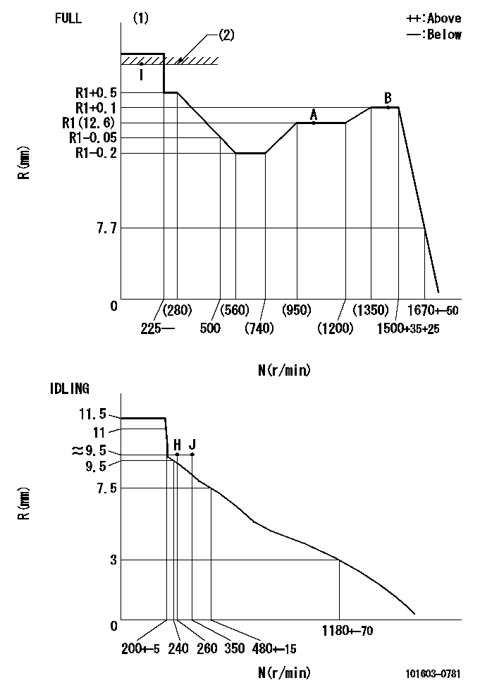
N:Pump speed
R:Rack position (mm)
(1)Torque cam stamping: T1
(2)RACK LIMIT
----------
T1=C32
----------
----------
T1=C32
----------
Speed control lever angle
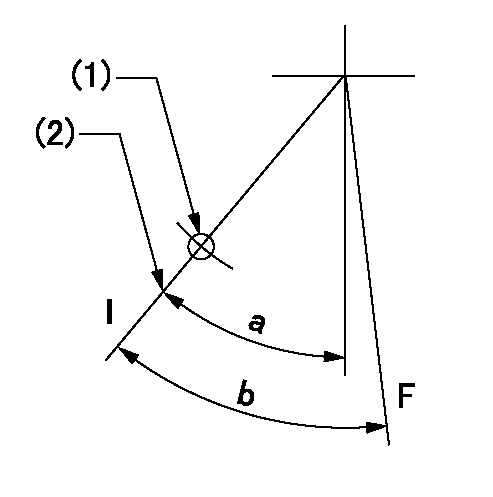
F:Full speed
I:Idle
(1)Use the hole at R = aa
(2)Stopper bolt set position 'H'
----------
aa=35mm
----------
a=42deg+-5deg b=(43deg)+-3deg
----------
aa=35mm
----------
a=42deg+-5deg b=(43deg)+-3deg
Stop lever angle

N:Pump normal
S:Stop the pump.
----------
----------
a=25deg+-5deg b=40deg+-5deg
----------
----------
a=25deg+-5deg b=40deg+-5deg
Timing setting

(1)Pump vertical direction
(2)Position of timer's threaded hole at No 1 cylinder's beginning of injection
(3)B.T.D.C.: aa
(4)-
----------
aa=12deg
----------
a=(60deg)
----------
aa=12deg
----------
a=(60deg)
Information:
When reporting the repair, use "PS61391" as the Part Number and "7777" as the Group Number. Use "96" as Warranty Claim Description Code and use "Z" as the SIMS Description Code.
The information supplied in this service letter may not be valid after the termination date of this program.Do not perform the work outlined in this Service Letter after the termination date without first contacting your Caterpillar product analyst.
TERMINATION DATE
30Jun2020
PROBLEM
The 398-1498 and 463-1678 Fuel Injection Pumps may fail on certain 320D 2 Excavators, equipped with C7.1M Engine. The fuel injection pump failure results in the engine not starting, hard to start, low power, or speed instability.
AFFECTED PRODUCT
Model Identification Number
320D 2 LCA01054-01108
TDZ00816-00829, 888-907, 911-923
PARTS NEEDED
Qty
Part Number Description
3 2323149 WASHER-SEALING
1 4631678 PUMP AS-F INJ
In order to allow equitable parts availability to all participating dealers, please limit your initial parts order to not exceed 2% of dealership population. This is an initial order recommendation only, and the ultimate responsibility for ordering the total number of parts needed to satisfy the program lies with the dealer.
ACTION REQUIRED
Refer REHS3767, Special Instruction, "Inspection of Fuel Injection Pumps on 3054C, C3.3, C4.4 (Mech), and C7.1 (Mech) Engines", to determine if the failure of fuel pump is caused by dirty fuel or customer's maintenance practices, and record facts as specified. Apply this Service Letter program only if the inspection reveals FIP failure that is not attributable to customer's maintenance or use of contaminated / bad fuel.
Remove the existing fuel injection pump, and install a new 463-1678 Fuel Injection Pump Assembly.
Refer to UENR0674, Disassembly and Assembly, C7.1 (Mech) Engines, "Fuel Injection Pump Remove - With Boost Control", and install procedure, in order to complete this Rework Procedure.
SERVICE CLAIM ALLOWANCES
Product smu/age whichever comes first Caterpillar Dealer Suggested Customer Suggested
Parts % Labor Hrs% Parts % Labor Hrs% Parts % Labor Hrs%
0-5000 hrs,
0-24 mo 100.0% 0.0% 0.0% 100.0% 0.0% 0.0%
This is a 8.0-hour job
PARTS DISPOSITION
Handle the parts in accordance with your Warranty Bulletin on warranty parts handling.