Information injection-pump assembly
ZEXEL
101603-0772
1016030772
ISUZU
1156018572
1156018572
Rating:
Cross reference number
ZEXEL
101603-0772
1016030772
ISUZU
1156018572
1156018572
Zexel num
Bosch num
Firm num
Name
Calibration Data:
Adjustment conditions
Test oil
1404 Test oil ISO4113 or {SAEJ967d}
1404 Test oil ISO4113 or {SAEJ967d}
Test oil temperature
degC
40
40
45
Nozzle and nozzle holder
105780-8140
Bosch type code
EF8511/9A
Nozzle
105780-0000
Bosch type code
DN12SD12T
Nozzle holder
105780-2080
Bosch type code
EF8511/9
Opening pressure
MPa
17.2
Opening pressure
kgf/cm2
175
Injection pipe
Outer diameter - inner diameter - length (mm) mm 6-2-600
Outer diameter - inner diameter - length (mm) mm 6-2-600
Overflow valve
131424-4920
Overflow valve opening pressure
kPa
127
107
147
Overflow valve opening pressure
kgf/cm2
1.3
1.1
1.5
Tester oil delivery pressure
kPa
157
157
157
Tester oil delivery pressure
kgf/cm2
1.6
1.6
1.6
Direction of rotation (viewed from drive side)
Right R
Right R
Injection timing adjustment
Direction of rotation (viewed from drive side)
Right R
Right R
Injection order
1-5-3-6-
2-4
Pre-stroke
mm
3.6
3.55
3.65
Beginning of injection position
Drive side NO.1
Drive side NO.1
Difference between angles 1
Cal 1-5 deg. 60 59.5 60.5
Cal 1-5 deg. 60 59.5 60.5
Difference between angles 2
Cal 1-3 deg. 120 119.5 120.5
Cal 1-3 deg. 120 119.5 120.5
Difference between angles 3
Cal 1-6 deg. 180 179.5 180.5
Cal 1-6 deg. 180 179.5 180.5
Difference between angles 4
Cyl.1-2 deg. 240 239.5 240.5
Cyl.1-2 deg. 240 239.5 240.5
Difference between angles 5
Cal 1-4 deg. 300 299.5 300.5
Cal 1-4 deg. 300 299.5 300.5
Injection quantity adjustment
Adjusting point
-
Rack position
11.5
Pump speed
r/min
900
900
900
Average injection quantity
mm3/st.
73.4
71.8
75
Max. variation between cylinders
%
0
-2.5
2.5
Basic
*
Fixing the rack
*
Standard for adjustment of the maximum variation between cylinders
*
Injection quantity adjustment_02
Adjusting point
H
Rack position
9.5+-0.5
Pump speed
r/min
275
275
275
Average injection quantity
mm3/st.
8
6.7
9.3
Max. variation between cylinders
%
0
-14
14
Fixing the rack
*
Standard for adjustment of the maximum variation between cylinders
*
Injection quantity adjustment_03
Adjusting point
A
Rack position
R1(11.5)
Pump speed
r/min
900
900
900
Average injection quantity
mm3/st.
73.4
72.4
74.4
Basic
*
Fixing the lever
*
Injection quantity adjustment_04
Adjusting point
I
Rack position
14+-0.5
Pump speed
r/min
150
150
150
Average injection quantity
mm3/st.
90
90
98
Fixing the lever
*
Rack limit
*
Timer adjustment
Pump speed
r/min
1350--
Advance angle
deg.
0
0
0
Remarks
Start
Start
Timer adjustment_02
Pump speed
r/min
1300
Advance angle
deg.
0.5
Timer adjustment_03
Pump speed
r/min
1400
Advance angle
deg.
2
1.5
2.5
Timer adjustment_04
Pump speed
r/min
1500
Advance angle
deg.
4.5
4
5
Remarks
Finish
Finish
Test data Ex:
Governor adjustment
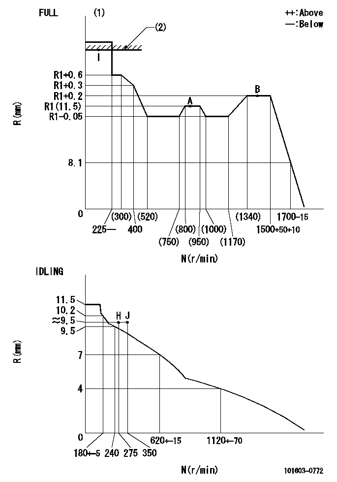
N:Pump speed
R:Rack position (mm)
(1)Torque cam stamping: T1
(2)RACK LIMIT
----------
T1=C73
----------
----------
T1=C73
----------
Speed control lever angle
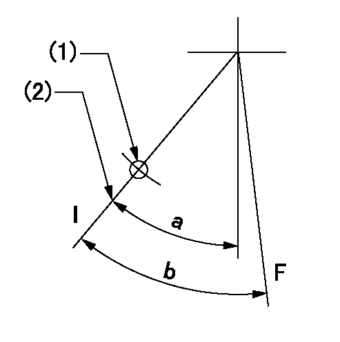
F:Full speed
I:Idle
(1)Use the hole at R = aa
(2)Stopper bolt set position 'H'
----------
aa=45mm
----------
a=21.5deg+-5deg b=35deg+-3deg
----------
aa=45mm
----------
a=21.5deg+-5deg b=35deg+-3deg
Stop lever angle

N:Pump normal
S:Stop the pump.
----------
----------
a=25deg+-5deg b=40deg+-5deg
----------
----------
a=25deg+-5deg b=40deg+-5deg
Timing setting

(1)Pump vertical direction
(2)Position of timer's threaded hole at No 1 cylinder's beginning of injection
(3)B.T.D.C.: aa
(4)-
----------
aa=12deg
----------
a=(60deg)
----------
aa=12deg
----------
a=(60deg)
Information:
1. Remove tube and elbow (1).2. Remove tube and oil sump (2).
Turn the crankshaft so the piston is down, and remove the ridge of carbon with emery cloth from each liner before removing the pistons. Damage can be caused to the pistons during removal by the build up of carbon if it is not removed.
3. Turn the crankshaft until the connecting rod cap to be removed is at bottom center.4. Remove connecting rod cap (3) from the connecting rod.
Put identification marks on the connecting rod caps as to their location in the engine. Keep the caps with their respective piston.
5. Push the connecting rod and piston away from the crankshaft until the piston rings are above the cylinder liner. Remove piston (4) and the connecting rod from the engine.
Use tape to hold the bearing halves together and to identify the number of the cylinder.
Install Pistons
1. Turn the crankshaft until the bearing journal for the piston to be installed is at bottom center.2. Put clean engine oil on the crankshaft journal and on the inside of the cylinder liner.3. Put clean engine oil on the piston rings and connecting rod bearings.4. Move the piston ring gaps 180° apart.5. Use tool (A), and put the piston and connecting rod in its original location in the cylinder block. Be sure the numbered side of the connecting rod is toward the right side of the engine. This is when viewed from the front of the engine.
Be sure the connecting rod bolts do not contact the crankshaft journal during installation of the piston.
6. Use a hammer handle, and lightly tap the piston into position.
When the connecting rod caps are installed, make sure the number on the side of the cap is next to the same number on the connecting rod. The numbers must be away from the camshaft.
7. Install connecting rod cap (1) and the nuts which hold it. Tighten the nuts to a torque value of: Cadmium plated nuts (silver color) - 100 N m (75 lb.ft).Phosphated nuts (dull black color) - 130 N m (95 lb.ft.).8. Follow the same procedure for installation of the remainder of the pistons. 9. Install tube and elbow (2). Install tube and oil sump (3).End By:a. install oil panb. install cylinder head assemblyDisassemble Pistons
Start By:a. remove pistons Put identification marks on all parts for correct assembly.1. Remove rings (1) from piston (2) with tool (A). 2. Remove retaining ring (3) from each side of the piston with tool (B).3. Remove pin (4) and connecting rod (5) from piston (2). 4. Remove bolts (7) from the connecting rod.5. Remove bushing (6) from connecting rod (5) with tool group (C).6. Check all of the parts of the piston and rod for damage and wear. See Specification for minimum and maximum wear dimensions.Assemble Pistons
1. Install bolts (1) in connecting rod (2).2. Install the bushing in connecting rod (2) with tool group (A) and a press. Hone the bushing to the correct size. See Specifications for the correct dimension. 3.