Information injection-pump assembly
ZEXEL
101603-0770
1016030770
ISUZU
1156018570
1156018570
Rating:
Cross reference number
ZEXEL
101603-0770
1016030770
ISUZU
1156018570
1156018570
Zexel num
Bosch num
Firm num
Name
Calibration Data:
Adjustment conditions
Test oil
1404 Test oil ISO4113 or {SAEJ967d}
1404 Test oil ISO4113 or {SAEJ967d}
Test oil temperature
degC
40
40
45
Nozzle and nozzle holder
105780-8140
Bosch type code
EF8511/9A
Nozzle
105780-0000
Bosch type code
DN12SD12T
Nozzle holder
105780-2080
Bosch type code
EF8511/9
Opening pressure
MPa
17.2
Opening pressure
kgf/cm2
175
Injection pipe
Outer diameter - inner diameter - length (mm) mm 6-2-600
Outer diameter - inner diameter - length (mm) mm 6-2-600
Overflow valve
132424-0620
Overflow valve opening pressure
kPa
157
123
191
Overflow valve opening pressure
kgf/cm2
1.6
1.25
1.95
Tester oil delivery pressure
kPa
157
157
157
Tester oil delivery pressure
kgf/cm2
1.6
1.6
1.6
Direction of rotation (viewed from drive side)
Right R
Right R
Injection timing adjustment
Direction of rotation (viewed from drive side)
Right R
Right R
Injection order
1-5-3-6-
2-4
Pre-stroke
mm
3.6
3.55
3.65
Beginning of injection position
Drive side NO.1
Drive side NO.1
Difference between angles 1
Cal 1-5 deg. 60 59.5 60.5
Cal 1-5 deg. 60 59.5 60.5
Difference between angles 2
Cal 1-3 deg. 120 119.5 120.5
Cal 1-3 deg. 120 119.5 120.5
Difference between angles 3
Cal 1-6 deg. 180 179.5 180.5
Cal 1-6 deg. 180 179.5 180.5
Difference between angles 4
Cyl.1-2 deg. 240 239.5 240.5
Cyl.1-2 deg. 240 239.5 240.5
Difference between angles 5
Cal 1-4 deg. 300 299.5 300.5
Cal 1-4 deg. 300 299.5 300.5
Injection quantity adjustment
Adjusting point
-
Rack position
12.5
Pump speed
r/min
1000
1000
1000
Average injection quantity
mm3/st.
76.5
74.9
78.1
Max. variation between cylinders
%
0
-2.5
2.5
Basic
*
Fixing the rack
*
Standard for adjustment of the maximum variation between cylinders
*
Injection quantity adjustment_02
Adjusting point
H
Rack position
9.5+-0.5
Pump speed
r/min
260
260
260
Average injection quantity
mm3/st.
8.1
6.8
9.4
Max. variation between cylinders
%
0
-14
14
Fixing the rack
*
Standard for adjustment of the maximum variation between cylinders
*
Injection quantity adjustment_03
Adjusting point
A
Rack position
R1(12.5)
Pump speed
r/min
1000
1000
1000
Average injection quantity
mm3/st.
76.5
75.5
77.5
Basic
*
Fixing the lever
*
Injection quantity adjustment_04
Adjusting point
I
Rack position
15.3+-0.
5
Pump speed
r/min
150
150
150
Average injection quantity
mm3/st.
92
92
100
Fixing the lever
*
Rack limit
*
Timer adjustment
Pump speed
r/min
1350--
Advance angle
deg.
0
0
0
Remarks
Start
Start
Timer adjustment_02
Pump speed
r/min
1300
Advance angle
deg.
0.5
Timer adjustment_03
Pump speed
r/min
1400
Advance angle
deg.
2
1.5
2.5
Timer adjustment_04
Pump speed
r/min
1500
Advance angle
deg.
4.5
4
5
Remarks
Finish
Finish
Test data Ex:
Governor adjustment
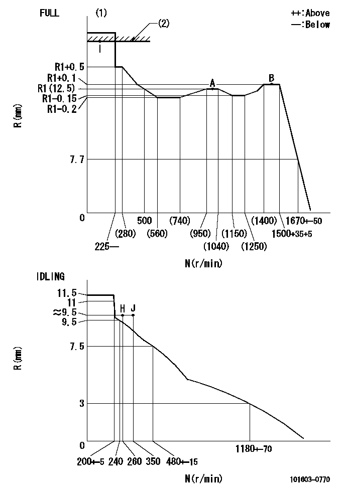
N:Pump speed
R:Rack position (mm)
(1)Torque cam stamping: T1
(2)RACK LIMIT
----------
T1=B25
----------
----------
T1=B25
----------
Speed control lever angle
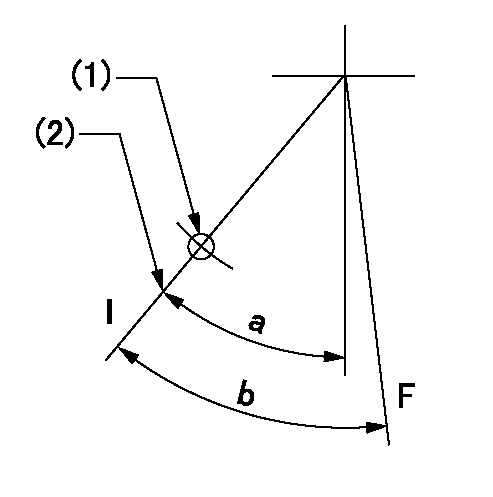
F:Full speed
I:Idle
(1)Use the hole at R = aa
(2)Stopper bolt set position 'H'
----------
aa=45mm
----------
a=21.5deg+-5deg b=(43deg)+-3deg
----------
aa=45mm
----------
a=21.5deg+-5deg b=(43deg)+-3deg
Stop lever angle

N:Pump normal
S:Stop the pump.
----------
----------
a=25deg+-5deg b=40deg+-5deg
----------
----------
a=25deg+-5deg b=40deg+-5deg
Timing setting

(1)Pump vertical direction
(2)Position of timer's threaded hole at No 1 cylinder's beginning of injection
(3)B.T.D.C.: aa
(4)-
----------
aa=12deg
----------
a=(60deg)
----------
aa=12deg
----------
a=(60deg)
Information:
Start By:a. remove engineb. remove crankshaft rear sealc. remove oil pump 1. Install the engine on tool (C). Fasten it in position at the flywheel end as shown.2. Remove bridges (1) and the seals. 3. Remove connecting rod bearing caps (2) and (3). Be sure the connecting rods, connecting rod caps and bearings are labeled so the parts can be matched at assembly. Be sure the location is marked on the main bearing caps before they are removed. The stamped location number is toward the camshaft. 4. Remove five main bearing caps (4). Remove the bearings from the main bearing caps, and remove the thrust washers from the center main bearing cap. Put identification marks on the bearings as to their location in the engine.5. Remove the connecting rod bolts, and push the pistons to the top of their stroke. Do not damage the crankshaft journals with the connecting rod bolts. 6. Remove the two upper thrust bearings (5). 7. Fasten a nylon strap and hoist to the crankshaft. The weight of the crankshaft is 27 kg (60 lb.).8. Carefully lift crankshaft (6) out of the engine, and store the crankshaft in a safe place. 9. Remove main bearing upper halves (7) from the engine block, and connecting rod bearing upper halves (8) from the connecting rods. Tape each bearing half to its respective lower bearing half. 10. Remove gear (9) from the crankshaft with tooling (A). Remove the key.11. Use tool (B) and quick dry solvent to clean the oil passages in the crankshaft.12. Clean the passage with quick dry solvent, and dry with compressed air.13. Inspect the crankshaft journals and thrust flange. See Engine Specifications.Install Crankshaft
1. Be sure all parts are clean.2. Install key (2) on crankshaft (3).3. Put crankshaft gear (1) in position with the timing mark toward the outside.
Original Crankshaft Replacement part service crankshafts may differ in appearance from the original crankshaft, but are functionally the same. 4. If the original main bearings are to be used, install bearing upper halves (4) in their original location. If new bearings are to be used, install the main bearing upper halves. Do not put oil on the bearings at this time. 5. Fasten a nylon strap and hoist to the crankshaft (5), and carefully put the crankshaft in place in the main bearing upper halves.6. Check main bearing clearances. Follow the procedures in Specifications.7. Fasten a nylon strap and hoist to the crankshaft, and lift the crankshaft so clean engine oil can be put on the bearing upper halves. 8. Install new thrust washers (6) on each side of the center main bearing location in the engine block. Be sure the bearing surface is toward the crankshaft and the smooth surface is toward the engine block. 9. Put new thrust washers (8) on each side of center main bearing cap (7). Be sure the tabs on the thrust washers are engaged with the grooves in the bearing cap.10. Put clean engine oil on the main bearing