Information injection-pump assembly
ZEXEL
101603-0760
1016030760
ISUZU
1156018550
1156018550
Rating:
Cross reference number
ZEXEL
101603-0760
1016030760
ISUZU
1156018550
1156018550
Zexel num
Bosch num
Firm num
Name
Calibration Data:
Adjustment conditions
Test oil
1404 Test oil ISO4113 or {SAEJ967d}
1404 Test oil ISO4113 or {SAEJ967d}
Test oil temperature
degC
40
40
45
Nozzle and nozzle holder
105780-8140
Bosch type code
EF8511/9A
Nozzle
105780-0000
Bosch type code
DN12SD12T
Nozzle holder
105780-2080
Bosch type code
EF8511/9
Opening pressure
MPa
17.2
Opening pressure
kgf/cm2
175
Injection pipe
Outer diameter - inner diameter - length (mm) mm 6-2-600
Outer diameter - inner diameter - length (mm) mm 6-2-600
Overflow valve
132424-0620
Overflow valve opening pressure
kPa
157
123
191
Overflow valve opening pressure
kgf/cm2
1.6
1.25
1.95
Tester oil delivery pressure
kPa
157
157
157
Tester oil delivery pressure
kgf/cm2
1.6
1.6
1.6
Direction of rotation (viewed from drive side)
Right R
Right R
Injection timing adjustment
Direction of rotation (viewed from drive side)
Right R
Right R
Injection order
1-5-3-6-
2-4
Pre-stroke
mm
3.4
3.35
3.45
Beginning of injection position
Drive side NO.1
Drive side NO.1
Difference between angles 1
Cal 1-5 deg. 60 59.25 60.25
Cal 1-5 deg. 60 59.25 60.25
Difference between angles 2
Cal 1-3 deg. 120 119.25 120.25
Cal 1-3 deg. 120 119.25 120.25
Difference between angles 3
Cal 1-6 deg. 180 179.25 180.25
Cal 1-6 deg. 180 179.25 180.25
Difference between angles 4
Cyl.1-2 deg. 240 239.25 240.25
Cyl.1-2 deg. 240 239.25 240.25
Difference between angles 5
Cal 1-4 deg. 300 299.25 300.25
Cal 1-4 deg. 300 299.25 300.25
Injection quantity adjustment
Adjusting point
-
Rack position
11.2
Pump speed
r/min
900
900
900
Average injection quantity
mm3/st.
78.5
76.9
80.1
Max. variation between cylinders
%
0
-2.5
2.5
Basic
*
Fixing the rack
*
Standard for adjustment of the maximum variation between cylinders
*
Injection quantity adjustment_02
Adjusting point
-
Rack position
9.7+-0.5
Pump speed
r/min
275
275
275
Average injection quantity
mm3/st.
9.4
8.1
10.7
Max. variation between cylinders
%
0
-14
14
Fixing the rack
*
Standard for adjustment of the maximum variation between cylinders
*
Remarks
Adjust only variation between cylinders; adjust governor according to governor specifications.
Adjust only variation between cylinders; adjust governor according to governor specifications.
Injection quantity adjustment_03
Adjusting point
A
Rack position
R1(11.2)
Pump speed
r/min
900
900
900
Average injection quantity
mm3/st.
78.5
77.5
79.5
Basic
*
Fixing the lever
*
Boost pressure
kPa
15.3
15.3
Boost pressure
mmHg
115
115
Injection quantity adjustment_04
Adjusting point
B
Rack position
R1-0.25
Pump speed
r/min
1500
1500
1500
Average injection quantity
mm3/st.
84.1
80.9
87.3
Fixing the lever
*
Boost pressure
kPa
15.3
15.3
Boost pressure
mmHg
115
115
Injection quantity adjustment_05
Adjusting point
C
Rack position
R1-0.5
Pump speed
r/min
550
550
550
Average injection quantity
mm3/st.
55.7
52.5
58.9
Fixing the lever
*
Boost pressure
kPa
15.3
15.3
Boost pressure
mmHg
115
115
Injection quantity adjustment_06
Adjusting point
I
Rack position
13+-0.5
Pump speed
r/min
150
150
150
Average injection quantity
mm3/st.
82
82
87
Fixing the lever
*
Rack limit
*
Boost compensator adjustment
Pump speed
r/min
600
600
600
Rack position
(R1-0.5)
-0.8
Boost pressure
kPa
2
2
4.7
Boost pressure
mmHg
15
15
35
Boost compensator adjustment_02
Pump speed
r/min
600
600
600
Rack position
(R1-0.5)
-0.6
Boost pressure
kPa
4.7
4.7
7.4
Boost pressure
mmHg
35
35
55
Boost compensator adjustment_03
Pump speed
r/min
600
600
600
Rack position
R1-0.5
Remarks
Measure actual boost pressure.
Measure actual boost pressure.
Timer adjustment
Pump speed
r/min
1300--
Advance angle
deg.
0
0
0
Remarks
Start
Start
Timer adjustment_02
Pump speed
r/min
1250
Advance angle
deg.
0.5
Timer adjustment_03
Pump speed
r/min
1350
Advance angle
deg.
0.7
0.2
1.2
Timer adjustment_04
Pump speed
r/min
1450
Advance angle
deg.
1.5
1.2
1.8
Remarks
Finish
Finish
Test data Ex:
Governor adjustment
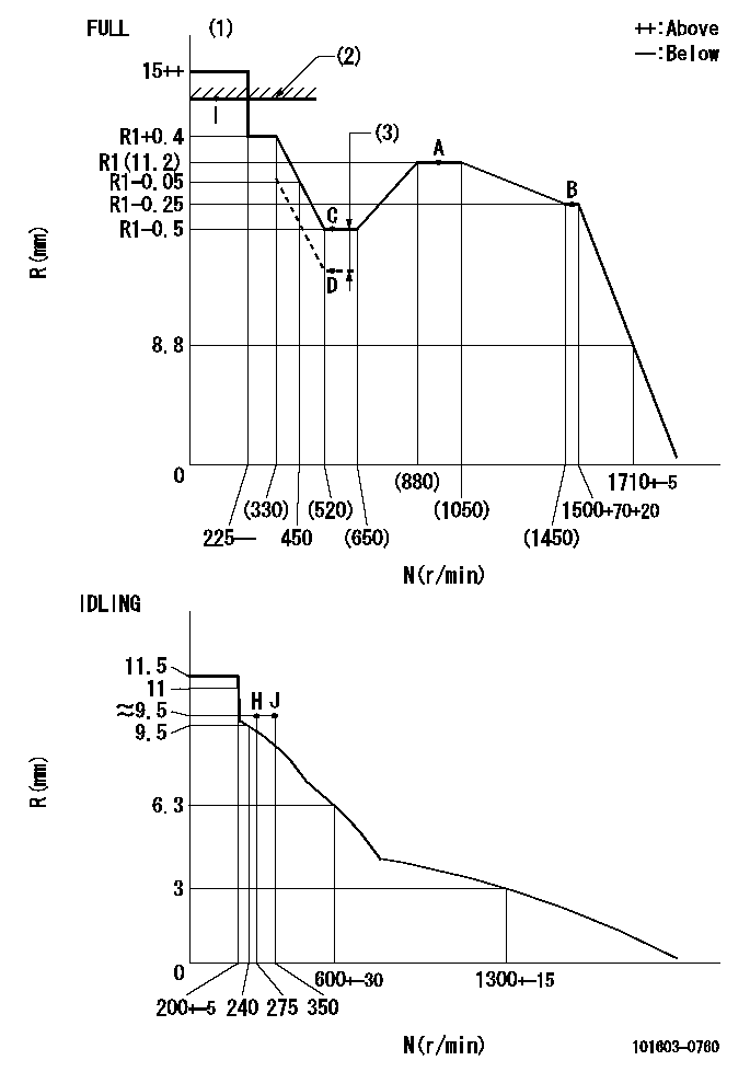
N:Pump speed
R:Rack position (mm)
(1)Torque cam stamping: T1
(2)RACK LIMIT
(3)Boost compensator stroke: BCL
----------
T1=B18 BCL=0.8+-0.1mm
----------
----------
T1=B18 BCL=0.8+-0.1mm
----------
Speed control lever angle

F:Full speed
I:Idle
(1)Use the hole at R = aa
(2)Stopper bolt set position 'H'
----------
aa=35mm
----------
a=40deg+-5deg b=34deg+-3deg
----------
aa=35mm
----------
a=40deg+-5deg b=34deg+-3deg
Stop lever angle

N:Pump normal
S:Stop the pump.
----------
----------
a=25deg+-5deg b=40deg+-5deg
----------
----------
a=25deg+-5deg b=40deg+-5deg
Timing setting

(1)Pump vertical direction
(2)Positions of coupling's threaded installation holes at No 1 cylinder's beginning of injection
(3)B.T.D.C.: aa
(4)-
----------
aa=13deg
----------
a=(60deg)
----------
aa=13deg
----------
a=(60deg)
Information:
Start By:a. remove timing gear cover 1. Remove bolt (1) that holds the relief valve.2. Remove bolts (2) that hold suction tube to the mounting bracket. 3. Use tool (A) to remove the retaining ring that holds idler gear (3). Remove idler gear (3).4. Inspect bushing (4) in idler gear (3). If bushing replacement is necessary, use tooling (B) to remove the bushing.5. Remove bolts (4) that hold oil pump (5) to the front main bearing cap, and remove oil pump (5). Use the reverse procedures of Steps 1 through 5 for installation of the oil pump.Disassemble Oil Pump
Start By:a. remove oil pump 1. Disconnect pump suction tube assembly (2) from oil pump (3).2. Disconnect pump pressure tube (1) from oil pump (3). 3. Remove relief valve (4).
The cap under cotter pin (5) is under spring force. To prevent personal injury, be careful to hold the cap when removing cotter pin (5).
4. Remove cotter pin (5). 5. Remove cap (6), spring (7) and plunger (8) from relief valve (4). The oil pump is serviced only as an assembly. See Specifications for more information on how to check the condition of the pump.Assemble Oil Pump
1. Install plunger (3), spring (2) and cap (1) into relief valve (4). Compress spring (2) with cap (1), and install cotter pin (5). 2. Put a new gasket on relief valve (4), and install tube (6). 3. Connect tube (6) to oil pump (8).4. Put a new gasket on oil pump (8), and install oil pump suction tube (7).End By:a. install oil pump