Information injection-pump assembly
ZEXEL
101603-0750
1016030750
ISUZU
1156018540
1156018540

Rating:
Cross reference number
ZEXEL
101603-0750
1016030750
ISUZU
1156018540
1156018540
Zexel num
Bosch num
Firm num
Name
Calibration Data:
Adjustment conditions
Test oil
1404 Test oil ISO4113 or {SAEJ967d}
1404 Test oil ISO4113 or {SAEJ967d}
Test oil temperature
degC
40
40
45
Nozzle and nozzle holder
105780-8140
Bosch type code
EF8511/9A
Nozzle
105780-0000
Bosch type code
DN12SD12T
Nozzle holder
105780-2080
Bosch type code
EF8511/9
Opening pressure
MPa
17.2
Opening pressure
kgf/cm2
175
Injection pipe
Outer diameter - inner diameter - length (mm) mm 6-2-600
Outer diameter - inner diameter - length (mm) mm 6-2-600
Overflow valve
132424-0620
Overflow valve opening pressure
kPa
157
123
191
Overflow valve opening pressure
kgf/cm2
1.6
1.25
1.95
Tester oil delivery pressure
kPa
157
157
157
Tester oil delivery pressure
kgf/cm2
1.6
1.6
1.6
Direction of rotation (viewed from drive side)
Right R
Right R
Injection timing adjustment
Direction of rotation (viewed from drive side)
Right R
Right R
Injection order
1-5-3-6-
2-4
Pre-stroke
mm
3.4
3.35
3.45
Beginning of injection position
Drive side NO.1
Drive side NO.1
Difference between angles 1
Cal 1-5 deg. 60 59.25 60.25
Cal 1-5 deg. 60 59.25 60.25
Difference between angles 2
Cal 1-3 deg. 120 119.25 120.25
Cal 1-3 deg. 120 119.25 120.25
Difference between angles 3
Cal 1-6 deg. 180 179.25 180.25
Cal 1-6 deg. 180 179.25 180.25
Difference between angles 4
Cyl.1-2 deg. 240 239.25 240.25
Cyl.1-2 deg. 240 239.25 240.25
Difference between angles 5
Cal 1-4 deg. 300 299.25 300.25
Cal 1-4 deg. 300 299.25 300.25
Injection quantity adjustment
Adjusting point
-
Rack position
11.2
Pump speed
r/min
900
900
900
Average injection quantity
mm3/st.
78.5
76.9
80.1
Max. variation between cylinders
%
0
-2.5
2.5
Basic
*
Fixing the rack
*
Standard for adjustment of the maximum variation between cylinders
*
Injection quantity adjustment_02
Adjusting point
-
Rack position
9.7+-0.5
Pump speed
r/min
275
275
275
Average injection quantity
mm3/st.
9.4
8.1
10.7
Max. variation between cylinders
%
0
-14
14
Fixing the rack
*
Standard for adjustment of the maximum variation between cylinders
*
Remarks
Adjust only variation between cylinders; adjust governor according to governor specifications.
Adjust only variation between cylinders; adjust governor according to governor specifications.
Injection quantity adjustment_03
Adjusting point
A
Rack position
R1(11.2)
Pump speed
r/min
900
900
900
Average injection quantity
mm3/st.
78.5
77.5
79.5
Basic
*
Fixing the lever
*
Boost pressure
kPa
15.3
15.3
Boost pressure
mmHg
115
115
Injection quantity adjustment_04
Adjusting point
B
Rack position
R1-0.25
Pump speed
r/min
1500
1500
1500
Average injection quantity
mm3/st.
84.1
80.9
87.3
Fixing the lever
*
Boost pressure
kPa
15.3
15.3
Boost pressure
mmHg
115
115
Injection quantity adjustment_05
Adjusting point
C
Rack position
R1-0.5
Pump speed
r/min
550
550
550
Average injection quantity
mm3/st.
55.7
52.5
58.9
Fixing the lever
*
Boost pressure
kPa
15.3
15.3
Boost pressure
mmHg
115
115
Injection quantity adjustment_06
Adjusting point
I
Rack position
13+-0.5
Pump speed
r/min
150
150
150
Average injection quantity
mm3/st.
82
82
87
Fixing the lever
*
Rack limit
*
Boost compensator adjustment
Pump speed
r/min
600
600
600
Rack position
(R1-0.5)
-0.8
Boost pressure
kPa
2
2
4.7
Boost pressure
mmHg
15
15
35
Boost compensator adjustment_02
Pump speed
r/min
600
600
600
Rack position
(R1-0.5)
-0.6
Boost pressure
kPa
4.7
4.7
7.4
Boost pressure
mmHg
35
35
55
Boost compensator adjustment_03
Pump speed
r/min
600
600
600
Rack position
R1-0.5
Remarks
Measure actual boost pressure.
Measure actual boost pressure.
Test data Ex:
Governor adjustment
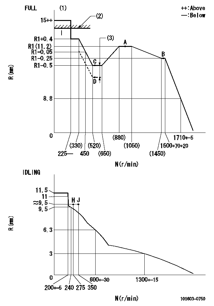
N:Pump speed
R:Rack position (mm)
(1)Torque cam stamping: T1
(2)RACK LIMIT
(3)Boost compensator stroke: BCL
----------
T1=B18 BCL=0.8+-0.1mm
----------
----------
T1=B18 BCL=0.8+-0.1mm
----------
Timer adjustment
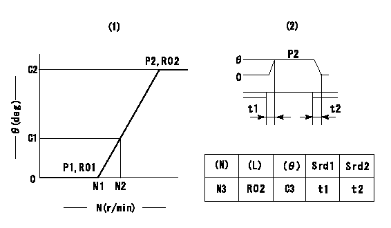
(1)Adjusting range
(2)Step response time
(N): Speed of the pump
(L): Load
(theta) Advance angle
(Srd1) Step response time 1
(Srd2) Step response time 2
1. Adjusting conditions for the variable timer
(1)Adjust the clearance between the pickup and the protrusion to L.
----------
L=1.5+-0.2mm N3=800r/min C3=(6.4deg) t1=2--sec. t2=2--sec.
----------
N1=1200++r/min N2=1500r/min P1=0kPa(0kgf/cm2) P2=392kPa(4kgf/cm2) C1=1.5--deg C2=6.4+-0.3deg R01=0/4load R02=4/4load
----------
L=1.5+-0.2mm N3=800r/min C3=(6.4deg) t1=2--sec. t2=2--sec.
----------
N1=1200++r/min N2=1500r/min P1=0kPa(0kgf/cm2) P2=392kPa(4kgf/cm2) C1=1.5--deg C2=6.4+-0.3deg R01=0/4load R02=4/4load
Speed control lever angle

F:Full speed
I:Idle
(1)Use the hole at R = aa
(2)Stopper bolt set position 'H'
----------
aa=35mm
----------
a=40deg+-5deg b=34deg+-3deg
----------
aa=35mm
----------
a=40deg+-5deg b=34deg+-3deg
Stop lever angle

N:Pump normal
S:Stop the pump.
----------
----------
a=25deg+-5deg b=40deg+-5deg
----------
----------
a=25deg+-5deg b=40deg+-5deg
0000001501 RACK SENSOR
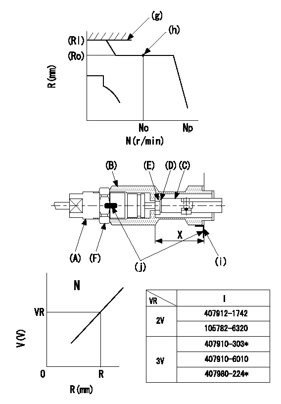
(g) rack limit
(h) Standard point
(i) pump end face
(j) Apply red paint.
Rack sensor adjustment (154610-0420)
1. Rack limit adjustment
(1)Fix the rack at the rack limit position Rl.
(2)Attach shim (D) [shim thickness standard (17.5 - R1] to rod (C) and tighten nut (E).
(3)Measure the distance X between the end face of the pump and the nut (E), and select a shim (D) so that X = 33-0.2mm.
(4)Release the rack, mount the joint (B) and fix.
(5)At this time, confirm that the shim (D) does not interfere with the joint (B).
2. Rack limit adjustment (amp-equipped type)
(1)Screw in the bobbin (A) until it contacts the joint (B).
(2)Fix the speed control lever at the full side and set the pump speed at No r/min.
(3)Adjust the depth that the bobbin (A) is screwed in so that the control unit's rack sensor output voltage is VR (V), then tighten the nut (F). (If equipped with a boost compensator, perform with boost pressure applied.)
(4)Apply red paint to both the joint (B) and the nut (F) join, and the joint (B) and the pump join.
----------
N=900r/min R=R1(11.2)mm VR=2+-0.01V
----------
----------
N=900r/min R=R1(11.2)mm VR=2+-0.01V
----------
Timing setting

(1)Pump vertical direction
(2)Positions of coupling's threaded installation holes at No 1 cylinder's beginning of injection
(3)-
(4)-
----------
----------
a=(60deg)
----------
----------
a=(60deg)
Information:
Start By:a. remove exhaust manifoldb. remove inlet manifoldc. remove fuel injection nozzle assembliesd. remove fuel filtere. remove water temperature regulatorf. remove cylinder head assembly 1. Put cylinder head assembly (1) in position on tool group (A). 2. Put compression on valve spring (2) with tool (C). 3. Remove spring locks (3). 4. Remove tool (C). Remove valve spring cap (2) and valve springs (4). 5. Remove washer (5) and O-ring seal (8) from valve (7).6. Remove seal (6). Remove valve (7). 7. Check the valve spring tension with tool (B). The outer spring force must be 180 9 N (40 2 lb.). The length of the spring under test force must be 27.4 mm (1.08 in.). The free length after test must be 45.2 mm (1.78 in.). The inner spring force must be 68.5 9 N (15.4 2 lb.). The length of the spring under test force must be 23.88 mm (.940 in.). The length after test must be 39.6 mm (1.56 in.).8. Do Steps 1 through 8 again for the remainder of the valves. If the cylinder head is equipped with removable valve guides, refer to module SENB8082-06, System Operating Testing And Adjusting Specifications, 4.236 And 4.2482 Diesel Engines For Lift Trucks.Install Valves
1. Put clean engine oil on the valve stems.2. Install valve (3), washer (2) and seal (1).
The closed coil of the spring must be toward the cylinder head.
3. Install springs (5) and valve spring cap (4). 4. Use tool (A), and put springs under compression, and install O-ring seal on the valve. Exhaust valves have an extra O-ring seal on them.
Locks (6) can be thrown from the valve when tool (A) is released if they are not in their correct position on the valve stem.
5. Use tool (B), and install locks (6) that hold the springs in place.6. Remove tool (A), and hit the top of the valve with a plastic hammer to be sure the locks are in their correct position on the valve.7. Do Steps 1 through 6 again for the remainder of the valves.End By:a. install cylinder head assemblyb. install water temperature regulatorc. install fuel filterd. install fuel injection nozzle assembliese. install inlet manifold