Information injection-pump assembly
ZEXEL
101603-0720
1016030720
ISUZU
1156018601
1156018601
Rating:
Service parts 101603-0720 INJECTION-PUMP ASSEMBLY:
1.
_
7.
COUPLING PLATE
8.
_
9.
_
11.
Nozzle and Holder
1-15300-104-2
12.
Open Pre:MPa(Kqf/cm2)
18.1(185)

15.
NOZZLE SET
Cross reference number
ZEXEL
101603-0720
1016030720
ISUZU
1156018601
1156018601
Zexel num
Bosch num
Firm num
Name
Calibration Data:
Adjustment conditions
Test oil
1404 Test oil ISO4113 or {SAEJ967d}
1404 Test oil ISO4113 or {SAEJ967d}
Test oil temperature
degC
40
40
45
Nozzle and nozzle holder
105780-8140
Bosch type code
EF8511/9A
Nozzle
105780-0000
Bosch type code
DN12SD12T
Nozzle holder
105780-2080
Bosch type code
EF8511/9
Opening pressure
MPa
17.2
Opening pressure
kgf/cm2
175
Injection pipe
Outer diameter - inner diameter - length (mm) mm 6-2-600
Outer diameter - inner diameter - length (mm) mm 6-2-600
Overflow valve opening pressure
kPa
157
123
191
Overflow valve opening pressure
kgf/cm2
1.6
1.25
1.95
Tester oil delivery pressure
kPa
157
157
157
Tester oil delivery pressure
kgf/cm2
1.6
1.6
1.6
Direction of rotation (viewed from drive side)
Right R
Right R
Injection timing adjustment
Direction of rotation (viewed from drive side)
Right R
Right R
Injection order
1-5-3-6-
2-4
Pre-stroke
mm
3.6
3.55
3.65
Beginning of injection position
Drive side NO.1
Drive side NO.1
Difference between angles 1
Cal 1-5 deg. 60 59.5 60.5
Cal 1-5 deg. 60 59.5 60.5
Difference between angles 2
Cal 1-3 deg. 120 119.5 120.5
Cal 1-3 deg. 120 119.5 120.5
Difference between angles 3
Cal 1-6 deg. 180 179.5 180.5
Cal 1-6 deg. 180 179.5 180.5
Difference between angles 4
Cyl.1-2 deg. 240 239.5 240.5
Cyl.1-2 deg. 240 239.5 240.5
Difference between angles 5
Cal 1-4 deg. 300 299.5 300.5
Cal 1-4 deg. 300 299.5 300.5
Injection quantity adjustment
Adjusting point
-
Rack position
11.3
Pump speed
r/min
900
900
900
Average injection quantity
mm3/st.
72.4
70.8
74
Max. variation between cylinders
%
0
-2.5
2.5
Basic
*
Fixing the rack
*
Standard for adjustment of the maximum variation between cylinders
*
Injection quantity adjustment_02
Adjusting point
H
Rack position
9.5+-0.5
Pump speed
r/min
285
285
285
Average injection quantity
mm3/st.
9.1
7.8
10.4
Max. variation between cylinders
%
0
-14
14
Fixing the rack
*
Standard for adjustment of the maximum variation between cylinders
*
Injection quantity adjustment_03
Adjusting point
A
Rack position
R1(11.3)
Pump speed
r/min
900
900
900
Average injection quantity
mm3/st.
72.4
71.4
73.4
Basic
*
Fixing the lever
*
Injection quantity adjustment_04
Adjusting point
I
Rack position
R2(14)
Pump speed
r/min
150
150
150
Average injection quantity
mm3/st.
88.5
88.5
96.5
Fixing the lever
*
Rack limit
*
Timer adjustment
Pump speed
r/min
1350--
Advance angle
deg.
0
0
0
Remarks
Start
Start
Timer adjustment_02
Pump speed
r/min
1300
Advance angle
deg.
0.5
Timer adjustment_03
Pump speed
r/min
1400
Advance angle
deg.
2
1.5
2.5
Timer adjustment_04
Pump speed
r/min
1500
Advance angle
deg.
4.5
4
5
Remarks
Finish
Finish
Test data Ex:
Governor adjustment
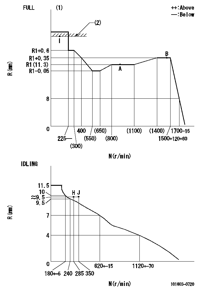
N:Pump speed
R:Rack position (mm)
(1)Torque cam stamping: T1
(2)RACK LIMIT
----------
T1=B50
----------
----------
T1=B50
----------
Speed control lever angle
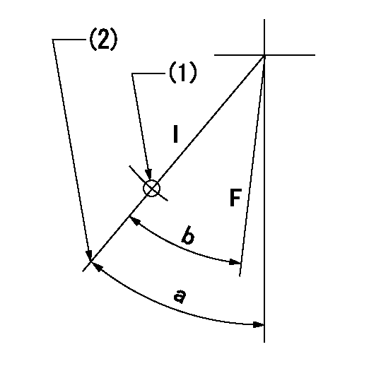
F:Full speed
I:Idle
(1)Use the hole at R = aa
(2)Stopper bolt set position 'H'
----------
aa=35mm
----------
a=42deg+-5deg b=42deg+-3deg
----------
aa=35mm
----------
a=42deg+-5deg b=42deg+-3deg
Stop lever angle

N:Pump normal
S:Stop the pump.
----------
----------
a=25deg+-5deg b=40deg+-5deg
----------
----------
a=25deg+-5deg b=40deg+-5deg
Timing setting

(1)Pump vertical direction
(2)Position of timer's threaded hole at No 1 cylinder's beginning of injection
(3)B.T.D.C.: aa
(4)-
----------
aa=12deg
----------
a=(60deg)
----------
aa=12deg
----------
a=(60deg)
Information:
Start By:a. remove rocker shaft and push rods 1. Remove circlip (1) and the washer from each end of the rocker shaft. 2. Put identification marks on the rocker arms, brackets and springs as to their location on the rocker shaft. Remove rocker arms (2), brackets (3) and springs (4) from each side of the rocker shaft.3. Remove screw (5) and rocker shaft oil feed connection (6). 4. Remove nut (7) and adjusting screw (8) from the rocker arm.5. Measure the bore of the bearings in each of the rocker arms. The bore must be 19.06 to 19.10 mm (.7505 to .7520 in.).6. Measure the diameter of the rocker shaft at each of the rocker arm locations. The diameter must be 19.01 to 19.04 mm (.7485 to .7495 in.). The maximum permissible clearance between the rocker arm bearings and shaft is 0.13 mm (.005 in.).7. If a replacement is needed, remove bushing (9) with tooling (A) and a press.Assemble Rocker Shaft
1. If a replacement was needed, make an alignment of oil hole (1) in the bushing with the oil hole in the rocker arm. Install new bushing (3) in the rocker arm with tooling (A) and a press. Check the bore dimension of the bushing in the rocker arm after installation. It must be 19.06 to 19.10 mm (.7505 to .7520 in.).
Do not turn the adjusting screw too far into the rocker arms. Damage to the valve can be the result after the rocker shaft and push rods have been installed in the engine.
2. Install adjusting screw (4) and nut (2) in the rocker arm. 3. Slide oil feed connection (9) on the rocker shaft. Install bolt (5) that holds it in place.4. Install springs (6), brackets (7) and rocker arms (8) in their original positions. 5. Install washer (11) and circlip (10) on each end of the rocker shaft.End By:a. install rocker shaft and push rods