Information injection-pump assembly
ZEXEL
101603-0580
1016030580
ISUZU
1156018131
1156018131

Rating:
Cross reference number
ZEXEL
101603-0580
1016030580
ISUZU
1156018131
1156018131
Zexel num
Bosch num
Firm num
Name
101603-0580
1156018131 ISUZU
INJECTION-PUMP ASSEMBLY
6QA1 * K
6QA1 * K
Calibration Data:
Adjustment conditions
Test oil
1404 Test oil ISO4113 or {SAEJ967d}
1404 Test oil ISO4113 or {SAEJ967d}
Test oil temperature
degC
40
40
45
Nozzle and nozzle holder
105780-8140
Bosch type code
EF8511/9A
Nozzle
105780-0000
Bosch type code
DN12SD12T
Nozzle holder
105780-2080
Bosch type code
EF8511/9
Opening pressure
MPa
17.2
Opening pressure
kgf/cm2
175
Injection pipe
Outer diameter - inner diameter - length (mm) mm 6-2-600
Outer diameter - inner diameter - length (mm) mm 6-2-600
Overflow valve
131424-0220
Overflow valve opening pressure
kPa
147
113
181
Overflow valve opening pressure
kgf/cm2
1.5
1.15
1.85
Tester oil delivery pressure
kPa
157
157
157
Tester oil delivery pressure
kgf/cm2
1.6
1.6
1.6
Direction of rotation (viewed from drive side)
Right R
Right R
Injection timing adjustment
Direction of rotation (viewed from drive side)
Right R
Right R
Injection order
1-4-2-6-
3-5
Pre-stroke
mm
3.7
3.65
3.75
Beginning of injection position
Drive side NO.1
Drive side NO.1
Difference between angles 1
Cal 1-4 deg. 60 59.5 60.5
Cal 1-4 deg. 60 59.5 60.5
Difference between angles 2
Cyl.1-2 deg. 120 119.5 120.5
Cyl.1-2 deg. 120 119.5 120.5
Difference between angles 3
Cal 1-6 deg. 180 179.5 180.5
Cal 1-6 deg. 180 179.5 180.5
Difference between angles 4
Cal 1-3 deg. 240 239.5 240.5
Cal 1-3 deg. 240 239.5 240.5
Difference between angles 5
Cal 1-5 deg. 300 299.5 300.5
Cal 1-5 deg. 300 299.5 300.5
Injection quantity adjustment
Adjusting point
A
Rack position
11.2
Pump speed
r/min
700
700
700
Average injection quantity
mm3/st.
108.1
107.1
109.1
Max. variation between cylinders
%
0
-2
2
Basic
*
Fixing the lever
*
Injection quantity adjustment_02
Adjusting point
B
Rack position
8.6+-0.5
Pump speed
r/min
225
225
225
Average injection quantity
mm3/st.
11.5
9.2
13.8
Max. variation between cylinders
%
0
-13
13
Fixing the rack
*
Injection quantity adjustment_03
Adjusting point
C
Rack position
-
Pump speed
r/min
150
150
150
Each cylinder's injection qty
mm3/st.
140
140
Fixing the lever
*
Remarks
After startup boost setting
After startup boost setting
Timer adjustment
Pump speed
r/min
500
Advance angle
deg.
0.3
Timer adjustment_02
Pump speed
r/min
600
Advance angle
deg.
0.8
0.1
0.8
Timer adjustment_03
Pump speed
r/min
700
Advance angle
deg.
0.8
0.3
1.3
Timer adjustment_04
Pump speed
r/min
900
Advance angle
deg.
2
1.5
2.5
Timer adjustment_05
Pump speed
r/min
1100
Advance angle
deg.
3.6
3.1
4.1
Timer adjustment_06
Pump speed
r/min
-
Advance angle
deg.
4
4
4
Remarks
Measure the actual speed, stop
Measure the actual speed, stop
Test data Ex:
Governor adjustment
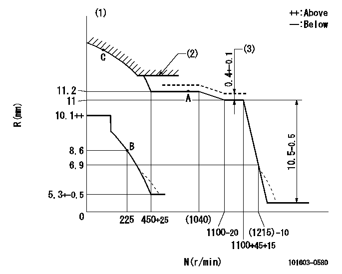
N:Pump speed
R:Rack position (mm)
(1)Damper spring setting: DL
(2)Excess fuel setting for starting: SXL
(3)Tamper proof (shaft setting) (at N = N1).
----------
DL=6.5+-0.5mm SXL=12.1+-0.1mm N1=1100r/min
----------
----------
DL=6.5+-0.5mm SXL=12.1+-0.1mm N1=1100r/min
----------
0000000901
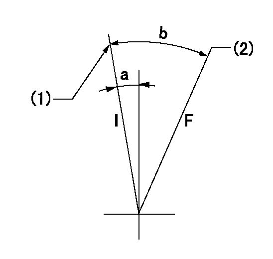
F:Full load
I:Idle
(1)Stopper bolt setting
(2)Attach the return spring to the upper hole and adjust.
----------
----------
a=4deg+-5deg b=21deg+-3deg
----------
----------
a=4deg+-5deg b=21deg+-3deg
Stop lever angle
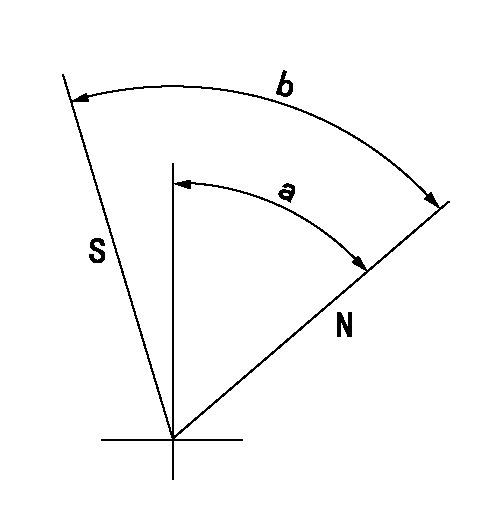
N:Pump normal
S:Stop the pump.
----------
----------
a=50.5deg+-5deg b=71deg+-5deg
----------
----------
a=50.5deg+-5deg b=71deg+-5deg
0000001501 TAMPER PROOF
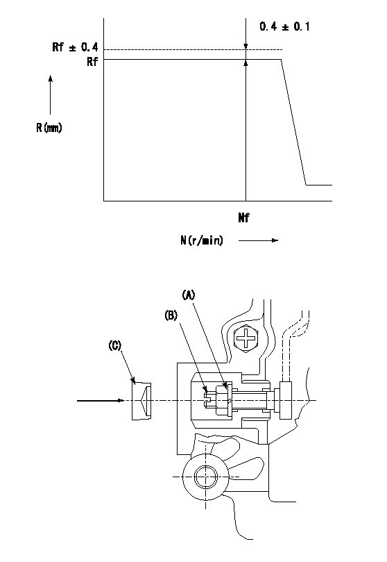
N:Pump speed (r/min)
R:Rack position (mm)
1. After governor adjustment, adjust the shaft as described below and stamp the cap.
(1)Turn the load lever stopper bolt determining the full rack position (R = Rf) 1~2 turns counterclockwise.
(2)Then, increase the full rack position.
(3)Operate the pump at N = Nf and turn the shaft (B) clockwise.
(4)Adjust so that full rack is Rf+0.4.
(5)Tighten nut (A) to the specified torque.
(6)Turn the stopper bolt clockwise the same amount that it was turned counter clockwise in (1).
(7)Then, align with the full rack position (R = Rf) and fix.
(8)Apply thread lock adhesive to the entire circumference of the cap (C) and tap it down to pressfit and seal it..
(9)Check for air tightness.
----------
Rf=11mm Nf=1100r/min
----------
----------
Rf=11mm Nf=1100r/min
----------
Information:
04Feb2016
U-58
A-46
D-55
O-52
Parts stock action only
PRODUCT IMPROVEMENT PROGRAM FOR REMOVING 398-1498 AND 463-1678 FUEL INJECTION PUMPS FROM DEALER PARTS STOCK
7750 PI70604
Caterpillar’s obligations under this Service Letter are subject to, and shall not apply in contravention of, the laws, rules, regulations, directives, ordinances, orders, or statutes of the United States, or of any other applicable jurisdiction, without recourse or liability with respect to Caterpillar.
When submitting claim for Parts Stock Action, Use the appropriate 99Z as the s/n, the appropriate Service Letter Program Number as the Part number in the Part Causing Failure field, "7751" as the Group Number, "56" as the Description Code.
The information supplied in this service letter may not be valid after the termination date of this program.Do not perform the work outlined in this Service Letter after the termination date without first contacting your Caterpillar product analyst.
TERMINATION DATE
31May2016
PROBLEM
The existing 398-1498 and 463-1678 Fuel Injection Pumps can fail. Fuel Injection Pumps up to and inclusive of component serial number 06369GJG, are suspect.
ACTION REQUIRED
Inspect all 398-1498 and 463-1678 Fuel Injection Pumps in dealer parts stock. Review the component serial number on each 398-1498 and 463-1678 Fuel Injection Pump. The Fuel Injection Pump component serial number can be located on the Fuel Injection Pump data plate, affixed to the side of the Fuel Injection Pump body.
The Fuel Injection Pump component serial number is alphanumeric, Refer to Image 1 for explanation on component serial number translation. In the given example the date code would translate to the following - 6369th pump built in July 2015.
NOTE - The build facility is not applicable in determining if the Fuel Injection Pump is suspect or not.
Refer to Image 2 for the build month and build year translation table.
Please action according to the following build month and build year color code -
Red = Remove from dealer part stock
Orange = Check Fuel Injection Pump Serial Number (06369 and below = Remove from dealer part stock / 06370 and Up = Return to dealer part stock).
Green = OK, Return to dealer part stock.
- If the Fuel Injection Pump is removed from dealer parts stock. Refer to the Service Claim Allowances and Parts Disposition.
- If the Fuel Injection Pump is returned to dealer parts stock, mark the box as inspected.
Image1
Image2
SERVICE CLAIM ALLOWANCES
Submit one claim for all Fuel Injection Pumps removed from dealer parts stock. Include the date code (e.g. 06369GJG) in the claim story for each Fuel Injection Pump removed from dealer parts stock.
PARTS DISPOSITION
NACD:
Hold all 398-1498 and 463-1678 Fuel Injection Pumps removed from dealer parts stock for a Parts Return Request (PRR). A Parts Return Request (PRR) will be issued to you through the Send-It-Back process after the claim is submitted. Make sure to list the service letter program number on the packing
Have questions with 101603-0580?
Group cross 101603-0580 ZEXEL
Isuzu
101603-0580
1156018131
INJECTION-PUMP ASSEMBLY
6QA1
6QA1