Information injection-pump assembly
ZEXEL
101603-0540
1016030540
ISUZU
1156014391
1156014391

Rating:
Service parts 101603-0540 INJECTION-PUMP ASSEMBLY:
1.
_

7.
COUPLING PLATE
8.
_
9.
_
11.
Nozzle and Holder
12.
Open Pre:MPa(Kqf/cm2)
18.1(185)

15.
NOZZLE SET
Cross reference number
ZEXEL
101603-0540
1016030540
ISUZU
1156014391
1156014391
Zexel num
Bosch num
Firm num
Name
Calibration Data:
Adjustment conditions
Test oil
1404 Test oil ISO4113 or {SAEJ967d}
1404 Test oil ISO4113 or {SAEJ967d}
Test oil temperature
degC
40
40
45
Nozzle and nozzle holder
105780-8140
Bosch type code
EF8511/9A
Nozzle
105780-0000
Bosch type code
DN12SD12T
Nozzle holder
105780-2080
Bosch type code
EF8511/9
Opening pressure
MPa
17.2
Opening pressure
kgf/cm2
175
Injection pipe
Outer diameter - inner diameter - length (mm) mm 6-2-600
Outer diameter - inner diameter - length (mm) mm 6-2-600
Overflow valve
132424-0620
Overflow valve opening pressure
kPa
157
123
191
Overflow valve opening pressure
kgf/cm2
1.6
1.25
1.95
Tester oil delivery pressure
kPa
157
157
157
Tester oil delivery pressure
kgf/cm2
1.6
1.6
1.6
Direction of rotation (viewed from drive side)
Right R
Right R
Injection timing adjustment
Direction of rotation (viewed from drive side)
Right R
Right R
Injection order
1-5-3-6-
2-4
Pre-stroke
mm
3.6
3.55
3.65
Beginning of injection position
Drive side NO.1
Drive side NO.1
Difference between angles 1
Cal 1-5 deg. 60 59.5 60.5
Cal 1-5 deg. 60 59.5 60.5
Difference between angles 2
Cal 1-3 deg. 120 119.5 120.5
Cal 1-3 deg. 120 119.5 120.5
Difference between angles 3
Cal 1-6 deg. 180 179.5 180.5
Cal 1-6 deg. 180 179.5 180.5
Difference between angles 4
Cyl.1-2 deg. 240 239.5 240.5
Cyl.1-2 deg. 240 239.5 240.5
Difference between angles 5
Cal 1-4 deg. 300 299.5 300.5
Cal 1-4 deg. 300 299.5 300.5
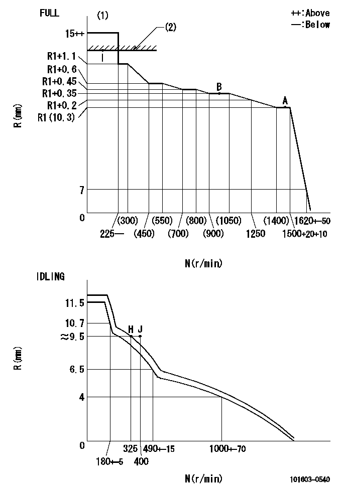
Injection quantity adjustment
Adjusting point
-
Rack position
10.3
Pump speed
r/min
1500
1500
1500
Average injection quantity
mm3/st.
48.9
47.3
50.5
Max. variation between cylinders
%
0
-2.5
2.5
Basic
*
Fixing the rack
*
Standard for adjustment of the maximum variation between cylinders
*
Injection quantity adjustment_02
Adjusting point
H
Rack position
9.5+-0.5
Pump speed
r/min
325
325
325
Average injection quantity
mm3/st.
8.7
7.4
10
Max. variation between cylinders
%
0
-14
14
Fixing the rack
*
Standard for adjustment of the maximum variation between cylinders
*
Injection quantity adjustment_03
Adjusting point
A
Rack position
R1(10.3)
Pump speed
r/min
1500
1500
1500
Average injection quantity
mm3/st.
48.9
47.9
49.9
Basic
*
Fixing the lever
*
Injection quantity adjustment_04
Adjusting point
B
Rack position
R1+0.35
Pump speed
r/min
1000
1000
1000
Average injection quantity
mm3/st.
54.3
51.1
57.5
Fixing the lever
*
Injection quantity adjustment_05
Adjusting point
I
Rack position
-
Pump speed
r/min
100
100
100
Average injection quantity
mm3/st.
60
60
65
Fixing the lever
*
Rack limit
*
Timer adjustment
Pump speed
r/min
350--
Advance angle
deg.
0
0
0
Remarks
Start
Start
Timer adjustment_02
Pump speed
r/min
300
Advance angle
deg.
0.5
Timer adjustment_03
Pump speed
r/min
900
Advance angle
deg.
2
1.5
2.5
Timer adjustment_04
Pump speed
r/min
1500
Advance angle
deg.
4
3.5
4.5
Remarks
Finish
Finish
Test data Ex:
Governor adjustment
N:Pump speed
R:Rack position (mm)
(1)Torque cam stamping: T1
(2)RACK LIMIT
----------
T1=B08
----------
----------
T1=B08
----------
Speed control lever angle
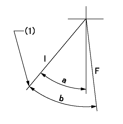
F:Full speed
I:Idle
(1)Stopper bolt set position 'H'
----------
----------
a=37deg+-5deg b=40deg+-3deg
----------
----------
a=37deg+-5deg b=40deg+-3deg
Stop lever angle
F:Full speed
I:Idle
(1)Stopper bolt set position 'H'
----------
----------
a=37deg+-5deg b=40deg+-3deg
----------
----------
a=37deg+-5deg b=40deg+-3deg
0000001501 TAMPER PROOF
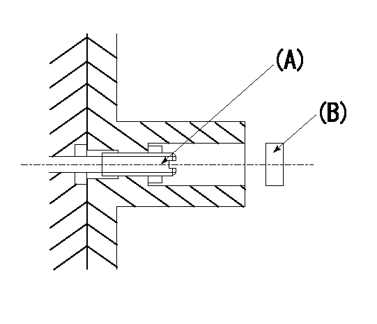
Tamper proof adjustment
(1)Set the full load screw at rack position Ra+0.4.
(2)Set the full load position Ra using screw (A).
----------
Ra=R1(10.3)mm
----------
----------
Ra=R1(10.3)mm
----------
Timing setting

(1)Pump vertical direction
(2)Position of timer's threaded hole at No 1 cylinder's beginning of injection
(3)B.T.D.C.: aa
(4)-
----------
aa=14deg
----------
a=(60deg)
----------
aa=14deg
----------
a=(60deg)
Information:
Before completing the attached Rework Procedure, review the safety actions in the Operation and Maintenance Manual for safety information and safe working practices before starting the rework.
If the head gasket has failed replace the head gasket and the fuel
injection pump.
If the head gasket has not failed replace the fuel injection pump only.
The 483-2326 Fuel Injection Pump has revised injection timing to reduce the peak cylinder pressure in the engine. It is essential that the pump is installed as per the Disassembly and Assembly, "Fuel Injection Pump - Install - Delphi DP210" to achieve the desired fuel injection timing.
SERVICE CLAIM ALLOWANCES
****Parts Stock****
Submit one claim for all parts removed from dealer parts stock.
****Affected Product****
Product smu/age whichever comes first Caterpillar Dealer Suggested Customer Suggested
Parts % Labor Hrs% Parts % Labor Hrs% Parts % Labor Hrs%
0-3000 hrs,
0-48 mo 100.0% 100.0% 0.0% 0.0% 0.0% 0.0%
This is a 5.5-hour job
For After failure, and additional 13.8 hours is allowed. A maximum of $100 will be allowed for machining of cylinder head face to achieve required surface finish after failure.
PARTS DISPOSITION
****Parts Stock****
Handle the parts in accordance with your Warranty Bulletin on warranty parts handling.
****Affected Product****
Handle the parts in accordance with your Warranty Bulletin on warranty parts handling.
Rework Procedure
If the head gasket has failed follow the rework procedure for both head gasket replacement and for fuel injection pump replacement
If the head gasket has not failed follow the rework procedure for fuel injection pump replacement only.
Head gasket replacement:
Confirm the head gasket has failed through removal of the cylinder head and visual inspection of the gasket. Remove cylinder head ? refer to Disassembly and Assembly, "Cylinder Head - Remove". Confirm head gasket has failed through visual inspection, as per the images shown in Image 1.1.1.
Clean the cylinder head face and the cylinder block face to remove any deposits on the gasket sealing surface using an appropriate cleaner. Do not use abrasive materials to remove the deposits during the cleaning process to ensure that the correct surface flatness is maintained.
Inspect cylinder head for flatness and distortion. Refer to Image 1.1.2 for surface finish. Refer to System Operation Testing and Adjusting, "Cylinder Head ? Inspect" for more information. Resurface the cylinder head if required as per Testing and Adjusting, "Cylinder Head ? Inspect".
Inspect cylinder block for surface finish on the top deck of the cylinder block. Refer to Image 1.1.2 for surface finish. If the cylinder block is within specifications, install a new 258-4946 Cylinder Head Gasket. If the block is not within specification, refer to Reuse And Salvage Guidelines, SEBF8076, "Specifications to Salvage Contact Surfaces of Cylinder Blocks" for more information.
Note: A 369-3705 Cylinder Head Gasket may be required, depending on reuse and salvage guidelines.
Follow Disassembly and Assembly, "Cylinder Head ? Install" with a new gasket as per above information.
Fuel injection pump replacement:
Follow Disassembly and Assembly, "Fuel Injection Pump - Remove - Delphi DP210". Do not reuse the fuel pump. Record removed fuel pump serial number in claim story. The fuel pump serial number is in the format "12345ABC".
Install the new 483-2326