Information injection-pump assembly
ZEXEL
101603-0500
1016030500
ISUZU
1156018010
1156018010

Rating:
Cross reference number
ZEXEL
101603-0500
1016030500
ISUZU
1156018010
1156018010
Zexel num
Bosch num
Firm num
Name
Calibration Data:
Adjustment conditions
Test oil
1404 Test oil ISO4113 or {SAEJ967d}
1404 Test oil ISO4113 or {SAEJ967d}
Test oil temperature
degC
40
40
45
Nozzle and nozzle holder
105780-8140
Bosch type code
EF8511/9A
Nozzle
105780-0000
Bosch type code
DN12SD12T
Nozzle holder
105780-2080
Bosch type code
EF8511/9
Opening pressure
MPa
17.2
Opening pressure
kgf/cm2
175
Injection pipe
Outer diameter - inner diameter - length (mm) mm 6-2-600
Outer diameter - inner diameter - length (mm) mm 6-2-600
Overflow valve opening pressure
kPa
157
123
191
Overflow valve opening pressure
kgf/cm2
1.6
1.25
1.95
Tester oil delivery pressure
kPa
157
157
157
Tester oil delivery pressure
kgf/cm2
1.6
1.6
1.6
Direction of rotation (viewed from drive side)
Left L
Left L
Injection timing adjustment
Direction of rotation (viewed from drive side)
Left L
Left L
Injection order
1-5-3-6-
2-4
Pre-stroke
mm
3.7
3.65
3.75
Beginning of injection position
Governor side NO.1
Governor side NO.1
Difference between angles 1
Cal 1-5 deg. 60 59.5 60.5
Cal 1-5 deg. 60 59.5 60.5
Difference between angles 2
Cal 1-3 deg. 120 119.5 120.5
Cal 1-3 deg. 120 119.5 120.5
Difference between angles 3
Cal 1-6 deg. 180 179.5 180.5
Cal 1-6 deg. 180 179.5 180.5
Difference between angles 4
Cyl.1-2 deg. 240 239.5 240.5
Cyl.1-2 deg. 240 239.5 240.5
Difference between angles 5
Cal 1-4 deg. 300 299.5 300.5
Cal 1-4 deg. 300 299.5 300.5
Injection quantity adjustment
Adjusting point
-
Rack position
12.4
Pump speed
r/min
700
700
700
Average injection quantity
mm3/st.
92.8
91.2
94.4
Max. variation between cylinders
%
0
-2.5
2.5
Basic
*
Fixing the rack
*
Standard for adjustment of the maximum variation between cylinders
*
Injection quantity adjustment_02
Adjusting point
H
Rack position
9.5+-0.5
Pump speed
r/min
250
250
250
Average injection quantity
mm3/st.
11.7
9.7
13.7
Max. variation between cylinders
%
0
-14
14
Fixing the rack
*
Standard for adjustment of the maximum variation between cylinders
*
Injection quantity adjustment_03
Adjusting point
A
Rack position
R1(12.4)
Pump speed
r/min
700
700
700
Average injection quantity
mm3/st.
92.8
91.8
93.8
Basic
*
Fixing the lever
*
Injection quantity adjustment_04
Adjusting point
B
Rack position
R1-0.2
Pump speed
r/min
550
550
550
Average injection quantity
mm3/st.
83.2
80
86.4
Fixing the lever
*
Injection quantity adjustment_05
Adjusting point
I
Rack position
R2(13.8)
Pump speed
r/min
100
100
100
Average injection quantity
mm3/st.
103
103
113
Fixing the lever
*
Rack limit
*
Timer adjustment
Pump speed
r/min
1150--
Advance angle
deg.
0
0
0
Remarks
Start
Start
Timer adjustment_02
Pump speed
r/min
1100
Advance angle
deg.
0.5
Timer adjustment_03
Pump speed
r/min
1250
Advance angle
deg.
3.1
2.6
3.6
Timer adjustment_04
Pump speed
r/min
1350
Advance angle
deg.
6
5.5
6.5
Remarks
Finish
Finish
Test data Ex:
Governor adjustment
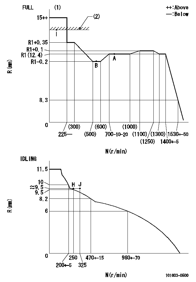
N:Pump speed
R:Rack position (mm)
(1)Torque cam stamping: T1
(2)RACK LIMIT
----------
T1=B01
----------
----------
T1=B01
----------
Speed control lever angle

F:Full speed
I:Idle
(1)Stopper bolt set position 'H'
----------
----------
a=18deg+-5deg b=33deg+-3deg
----------
----------
a=18deg+-5deg b=33deg+-3deg
Stop lever angle
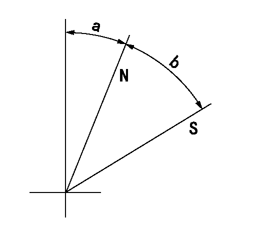
N:Pump normal
S:Stop the pump.
----------
----------
a=25deg+-5deg b=40deg+-5deg
----------
----------
a=25deg+-5deg b=40deg+-5deg
Timing setting

(1)Pump vertical direction
(2)Position of timer's threaded hole at No 1 cylinder's beginning of injection
(3)-
(4)-
----------
----------
a=(30deg)
----------
----------
a=(30deg)
Information:
Fuel Filter Group
(1) Remove clips (1) and (2). Remove tube assembly (3) and elbow (4) from the fuel transfer pump on the replacement engine. Installation of new line is shown in Fuel Lines Group, Page 8.Fuel Tank Group
(1) Remove the fuel tank from the machine; see the Service Manual. (2) Fabricate boss (1) to the dimensions shown. Make 1/8" - 27 NPTF threads in one end. (3) Drill a 20.0 mm Ø (0.78" Ø) hole (A) through the bottom of the tank as shown. (4) Put boss (1) in hole (A) with the threaded end extending below the bottom of the full tank as shown. Make a 3.0 mm (0.12") fillet weld all around the boss.(5) Clean and install the fuel tank; see the Service Manual.Fuel Lines Group
(1) Remove fuel inlet hose (1) and tube assembly (2) from tube (A). (2) Install 307946 Elbow (3) and a 3J7354 Seal in the fuel transfer pump. Install 2V4869 Fitting (4) on elbow (3). Cut a 360.0 mm (14.17") length of 5P1465 Hose (5), and connect it to fitting (4) and tube assembly (A) with the former clamps.(3) Install 6D238 Valve Assembly (7) in the boss installed in the fuel tank (see Step 4, Page 7). Fasten 5G5681 Tube (8) to valve assembly (7). Use L2072 Clamp (9) to hold the other end of tube (8) in position. Install clamp (9) under bolt (10).(4) Install 307941 Elbow (11) and a 3J7354 Seal in the fuel return port of the fuel injection pump housing. Install 2V4869 Fitting (12) on elbow (11).(5) Cut a 520.0 mm (20.47") length of 5P1465 Hose (13), and connect it to fitting (12) and tube (8) with a 1P4278 Clamp (14). An optional step to the above procedure is to connect a 60.0 mm (2.36") length of 5P189 Tube to valve assembly (7). Cut a 2000.0 mm (78.75") length of 5P6442 Hose and connect it to 2V4869 Fitting (12) and to the 5P189 Tube with a 1P4278 Clamp. Tie the hose to the machine to prevent damage to the hose.Electrical System
(1) For all machines, connect the alternator wire of the harness to the alternator.(2) For machines 80U1-80U6734, remove the original voltage regulator. Put tape over the wire connection to the wiring harness so it will be out of the way. The alternator for this engine has a built in voltage regulator so the original voltage regulator is not needed for the electrical system.Flywheel Group (For Replacement of 7N9437, 1W163 or 2W7488 Engine Arrangements)
(1) Remove the flywheel from the new replacement engine.(2) Install a new 7W2290 Flywheel Assembly, and fasten it to the crankshaft with four T489 Bolts. See the Service Manual for the procedure and the bolt torque. If necessary, use of the former flywheel from the engine being replaced is acceptable.Installation Of Ether Starting Aid Group
The ether starting aid is no longer a required component of direct injection engine arrangements.(1) If the machine is equipped with an ether starting aid group, its reuse is optional. To reuse,