Information injection-pump assembly
ZEXEL
101603-0442
1016030442
ISUZU
1156017703
1156017703
Rating:
Service parts 101603-0442 INJECTION-PUMP ASSEMBLY:
1.
_
7.
COUPLING PLATE
8.
_
9.
_
11.
Nozzle and Holder
1-15300-104-2
12.
Open Pre:MPa(Kqf/cm2)
18.1{185}

15.
NOZZLE SET
Cross reference number
ZEXEL
101603-0442
1016030442
ISUZU
1156017703
1156017703
Zexel num
Bosch num
Firm num
Name
Calibration Data:
Adjustment conditions
Test oil
1404 Test oil ISO4113 or {SAEJ967d}
1404 Test oil ISO4113 or {SAEJ967d}
Test oil temperature
degC
40
40
45
Nozzle and nozzle holder
105780-8140
Bosch type code
EF8511/9A
Nozzle
105780-0000
Bosch type code
DN12SD12T
Nozzle holder
105780-2080
Bosch type code
EF8511/9
Opening pressure
MPa
17.2
Opening pressure
kgf/cm2
175
Injection pipe
Outer diameter - inner diameter - length (mm) mm 6-2-600
Outer diameter - inner diameter - length (mm) mm 6-2-600
Overflow valve opening pressure
kPa
157
123
191
Overflow valve opening pressure
kgf/cm2
1.6
1.25
1.95
Tester oil delivery pressure
kPa
157
157
157
Tester oil delivery pressure
kgf/cm2
1.6
1.6
1.6
Direction of rotation (viewed from drive side)
Right R
Right R
Injection timing adjustment
Direction of rotation (viewed from drive side)
Right R
Right R
Injection order
1-5-3-6-
2-4
Pre-stroke
mm
3.6
3.55
3.65
Beginning of injection position
Drive side NO.1
Drive side NO.1
Difference between angles 1
Cal 1-5 deg. 60 59.5 60.5
Cal 1-5 deg. 60 59.5 60.5
Difference between angles 2
Cal 1-3 deg. 120 119.5 120.5
Cal 1-3 deg. 120 119.5 120.5
Difference between angles 3
Cal 1-6 deg. 180 179.5 180.5
Cal 1-6 deg. 180 179.5 180.5
Difference between angles 4
Cyl.1-2 deg. 240 239.5 240.5
Cyl.1-2 deg. 240 239.5 240.5
Difference between angles 5
Cal 1-4 deg. 300 299.5 300.5
Cal 1-4 deg. 300 299.5 300.5
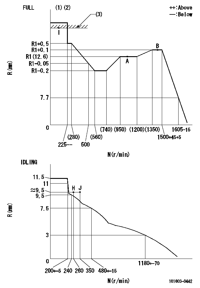
Injection quantity adjustment
Adjusting point
-
Rack position
12.6
Pump speed
r/min
1000
1000
1000
Average injection quantity
mm3/st.
76.8
75.2
78.4
Max. variation between cylinders
%
0
-2.5
2.5
Basic
*
Fixing the rack
*
Standard for adjustment of the maximum variation between cylinders
*
Injection quantity adjustment_02
Adjusting point
H
Rack position
9.5+-0.5
Pump speed
r/min
260
260
260
Average injection quantity
mm3/st.
8.1
6.8
9.4
Max. variation between cylinders
%
0
-14
14
Fixing the rack
*
Standard for adjustment of the maximum variation between cylinders
*
Remarks
Adjust only variation between cylinders; adjust governor according to governor specifications.
Adjust only variation between cylinders; adjust governor according to governor specifications.
Injection quantity adjustment_03
Adjusting point
A
Rack position
R1(12.6)
Pump speed
r/min
1000
1000
1000
Average injection quantity
mm3/st.
76.8
75.8
77.8
Basic
*
Fixing the lever
*
Injection quantity adjustment_04
Adjusting point
I
Rack position
15.3+-0.
5
Pump speed
r/min
150
150
150
Average injection quantity
mm3/st.
92
92
100
Fixing the lever
*
Rack limit
*
Timer adjustment
Pump speed
r/min
1350--
Advance angle
deg.
0
0
0
Remarks
Start
Start
Timer adjustment_02
Pump speed
r/min
1300
Advance angle
deg.
0.5
Timer adjustment_03
Pump speed
r/min
1400
Advance angle
deg.
2
1.5
2.5
Timer adjustment_04
Pump speed
r/min
1500
Advance angle
deg.
4.5
4
5
Remarks
Finish
Finish
Test data Ex:
Governor adjustment
N:Pump speed
R:Rack position (mm)
(1)Torque cam stamping: T1
(2)Torque control stroke: L1
(3)RACK LIMIT
----------
T1=C32 L1=(1)+-0.05mm
----------
----------
T1=C32 L1=(1)+-0.05mm
----------
Speed control lever angle
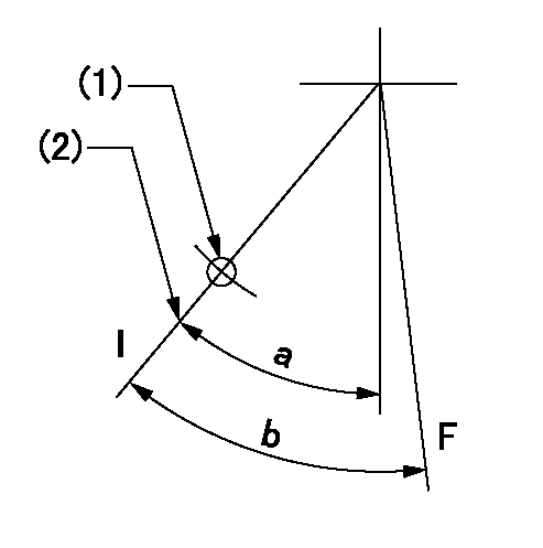
F:Full speed
I:Idle
(1)Use the hole at R = aa
(2)Stopper bolt set position 'H'
----------
aa=35mm
----------
a=42deg+-5deg b=(43deg)+-3deg
----------
aa=35mm
----------
a=42deg+-5deg b=(43deg)+-3deg
Stop lever angle

N:Pump normal
S:Stop the pump.
----------
----------
a=25deg+-5deg b=40deg+-5deg
----------
----------
a=25deg+-5deg b=40deg+-5deg
0000001501 VARIABLE TORQUE CONTROL
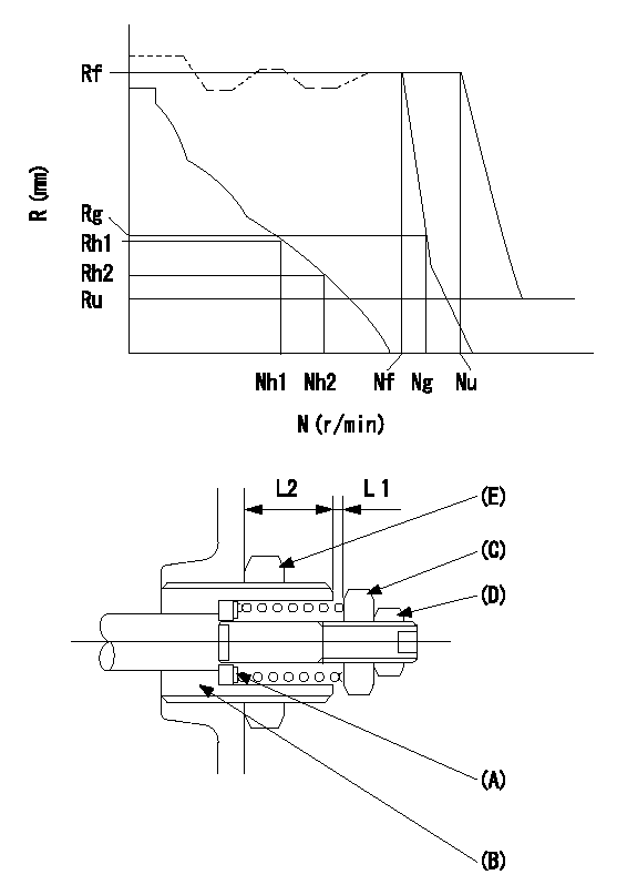
N:Pump speed (r/min)
R:Rack position (mm)
Adjusting shim A
Guide screw B
(c) Nut
(d) Nut
(e) nut
Torque control spring adjustment method for model responding to speed droop
[Advice]
Confirm that adjusting shim (A) thickness t = 1.3~1.5 mm is assembled before beginning adjustment.
(1)Temporary idle lever position setting
1. Refer to the RLD type governor service manual (Publication no. EE13E-11083).
(2)Idling spring adjustment
1. Refer to the RLD type governor service manual (Publication no. EE13E-11083).
(3)Governor spring setting adjustment
1. Temporarily fix so that the governor shaft's guide screw B protrudes L2 (18 mm) from the end of the governor.
2. Set the control lever where it contacts the idle stopper bolt.
3. Increase the speed to Nh2+100 r/min or more.
4. Adjust using the two nuts C and D so that L1 = 0.3+0.5 mm and fix temporarily.
5. Adjust the protrusion L2 of the guide screw (B) so that the rack position at Nh1 is Rh1 and at Nh2 is Rh2. Then fix using the nut (E).
6. Further increase the speed and readjust the two nuts (C) and (D) so that there is no change in L1 until Nf+50 r/min. Then fix temporarily.
[Advice]
When L1 becomes smaller while speed is increasing to Nf+50 r/min, decrease speed by Nh2+100 r/min.
Adjust so that L1 is even smaller, then again increase speed to Nf+50 r/min and confirm that L1 does not change.
(4)Full load position setting
1. Refer to the RLD type governor service manual (Publication no. EE13E-11083).
(5)Torque control spring adjustment
1. Set the control lever so that it contacts the full speed stopper bolt.
2. At the specified speed Nf, adjust using the full speed stopper bolt so that governing begins, then fix temporarily.
3. Increase the speed and adjust using the two nuts (C) and (D) so that the rack position Rg can be obtained at the specified speed Ng. Fix temporarily.
4. Decrease the speed and confirm the governing point (the beginning of governing point) at the specified speed Nf.
5. Set the speed at Nf-50 r/min.
6. Measure the torque control stroke (L1) and adjust to the specified stroke (L1) using the shim (A).
7. After completing shim adjustment, repeat the above adjustment using the two nuts.
8. After confirming the specifications Nf and Ng, fix the two nuts (C) and (D).
9. In this condition, increase the speed and confirm that R = 0 can be obtained.
(6)Full speed lever position setting
1. Set the control lever so that it contacts the full speed stopper bolt.
2. At the specified speed Nu, adjust using the full speed stopper bolt so that governing begins, then fix temporarily
3. Increase the speed and confirm that the specified rack position Ru can be obtained.
4. Adjust using the full speed stopper bolt so that governing begins at the specified speed Nf, then fix.
5. Confirm that the result is the same as that in '(5) Torque control spring adjustment.'
6. Confirm that the control lever operating angle is within the specifications.
(7)Rack limit adjustment
1. Refer to the RLD type governor service manual (Publication no. EE13E-11083).
----------
----------
----------
----------
Timing setting

(1)Pump vertical direction
(2)Position of timer's threaded hole at the No. 1 cylinder's beginning of injection
(3)B.T.D.C.: aa
(4)-
----------
aa=12deg
----------
a=(60deg)
----------
aa=12deg
----------
a=(60deg)
Information:
This instruction is written for electronic technicians only, and must not be used by service personnel with no training or knowledge of electronics. For repairs that can be done by the Caterpillar Dealer Serviceman, with no knowledge of electronics, see Special Instruction Form SMHS6964 "Using 1P3500 and 2P8280 Injection Timing Groups."As an aid to the technician for troubleshooting the inverter and timing light, the following information is given in this instruction:1. Circuit board illustrations showing the position of each of the components and the test points (T) for using a voltmeter or an oscilloscope.2. Schematics of the electrical circuit so the technician can easily follow the sequence of the circuit.3. Test point values.4. Electrical parts replacement information.5. Timing light calibration procedure.Timing Light
1P3500 And 2P8280 Timing Lights - Electrical Schematic, Test Points And Parts List
Inverter - Electrical Schematic, Test Points And Parts List
There is a two position switch that is marked ADV.-RPM on the side of the 1P3499 Timing Light. When the timing light is in use, operation of the ADV.-RPM switch is as follows:RPM Position
A fuel injection pulse opens the switch in the transducer and starts a positive pulse (TP9) of fixed duration, from the monostable composed of Q2 and Q3. This pulse turns on a transistor switch Q4, allowing current to pass through meter M1, which mechanically averages pulses from an operating engine, and is calibrated to read RPM. Switch S2 grounds the gate of SCR1 to prevent the flash tube from strobing.ADV. Position
A fuel injection pulse again starts a pulse from the monostable. Adjustment of R7, the TIME-ADVANCE control, now determines the pulse duration from the monostable. When R7 is adjusted so that TDC on the damper coincides with the pointer on the block of an operating engine, the monostable pulse duration is exactly the same as the fuel system advance measured in seconds. Transistor switch Q4 again turns on, allowing current to pass through meter M1, causing a meter indicator that is calibrated in degrees of advance instead of seconds.Electrical Calibration Procedure
Before the electrical calibration can be done, the following equipment must be obtained.1) Oscilloscope with triggered sweep. Heath Co. M/N SO-4530 or equivalent.2) Signal generator. Heath M/N SG-72A or equivalent.3) Electronic counter. Data Precision M/N 5740 or equivalent.4) Electronic switch (dealer built).Calibration Procedure
(1) Hold the 1P3499 Timing Light in the same position (about a 45° angle) as if measuring the timing advance on an engine, and check the mechanical meter zero. Make an adjustment to zero if necessary. (2) To remove the protective rubber boot from the flash tube, twist the rubber boot and pull it away from the timing light as shown. (3) Remove the right side (side that has the serial number tag) of the timing light case.(4) Connect the 1P3499 Timing Light to a circuit like the one that follows. This will simulate (be the same as) a fuel flow transducer on an engine that is operating at 2400 RPM. (5) Turn the TIME-ADV. control counterclockwise (CCW) to its minimum