Information injection-pump assembly
ZEXEL
101603-0311
1016030311
ISUZU
1156018051
1156018051
Rating:
Cross reference number
ZEXEL
101603-0311
1016030311
ISUZU
1156018051
1156018051
Zexel num
Bosch num
Firm num
Name
Calibration Data:
Adjustment conditions
Test oil
1404 Test oil ISO4113 or {SAEJ967d}
1404 Test oil ISO4113 or {SAEJ967d}
Test oil temperature
degC
40
40
45
Nozzle and nozzle holder
105780-8140
Bosch type code
EF8511/9A
Nozzle
105780-0000
Bosch type code
DN12SD12T
Nozzle holder
105780-2080
Bosch type code
EF8511/9
Opening pressure
MPa
17.2
Opening pressure
kgf/cm2
175
Injection pipe
Outer diameter - inner diameter - length (mm) mm 6-2-600
Outer diameter - inner diameter - length (mm) mm 6-2-600
Overflow valve opening pressure
kPa
157
123
191
Overflow valve opening pressure
kgf/cm2
1.6
1.25
1.95
Tester oil delivery pressure
kPa
157
157
157
Tester oil delivery pressure
kgf/cm2
1.6
1.6
1.6
Direction of rotation (viewed from drive side)
Right R
Right R
Injection timing adjustment
Direction of rotation (viewed from drive side)
Right R
Right R
Injection order
1-5-3-6-
2-4
Pre-stroke
mm
3.6
3.55
3.65
Beginning of injection position
Drive side NO.1
Drive side NO.1
Difference between angles 1
Cal 1-5 deg. 60 59.5 60.5
Cal 1-5 deg. 60 59.5 60.5
Difference between angles 2
Cal 1-3 deg. 120 119.5 120.5
Cal 1-3 deg. 120 119.5 120.5
Difference between angles 3
Cal 1-6 deg. 180 179.5 180.5
Cal 1-6 deg. 180 179.5 180.5
Difference between angles 4
Cyl.1-2 deg. 240 239.5 240.5
Cyl.1-2 deg. 240 239.5 240.5
Difference between angles 5
Cal 1-4 deg. 300 299.5 300.5
Cal 1-4 deg. 300 299.5 300.5
Injection quantity adjustment
Adjusting point
A
Rack position
8.9
Pump speed
r/min
1000
1000
1000
Average injection quantity
mm3/st.
61.3
59.8
62.8
Max. variation between cylinders
%
0
-2.5
2.5
Basic
*
Fixing the lever
*
Injection quantity adjustment_02
Adjusting point
B
Rack position
6.7+-0.5
Pump speed
r/min
290
290
290
Average injection quantity
mm3/st.
9.2
7.9
10.5
Max. variation between cylinders
%
0
-14
14
Fixing the rack
*
Injection quantity adjustment_03
Adjusting point
C
Rack position
-
Pump speed
r/min
150
150
150
Average injection quantity
mm3/st.
50
50
Fixing the lever
*
Remarks
After startup boost setting
After startup boost setting
Timer adjustment
Pump speed
r/min
350--
Advance angle
deg.
0
0
0
Remarks
Start
Start
Timer adjustment_02
Pump speed
r/min
300
Advance angle
deg.
0.5
Timer adjustment_03
Pump speed
r/min
900
Advance angle
deg.
2
1.5
2.5
Timer adjustment_04
Pump speed
r/min
1300
Advance angle
deg.
4
3.5
4.5
Remarks
Finish
Finish
Test data Ex:
Governor adjustment
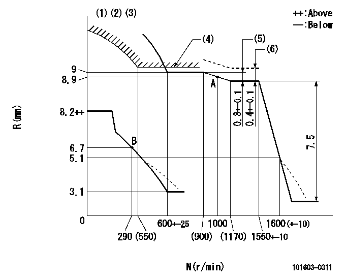
N:Pump speed
R:Rack position (mm)
(1)Lever ratio: RT
(2)Target shim dimension: TH
(3)Damper spring setting: DL
(4)Excess fuel setting for starting: SXL
(5)Rack difference between N = N1 and N = N2
(6)Tamper proof (shaft setting) (at N = N3).
----------
RT=1 TH=1.5mm DL=3.5-0.2mm SXL=9+0.2mm N1=1300r/min N2=850r/min N3=1300r/min
----------
----------
RT=1 TH=1.5mm DL=3.5-0.2mm SXL=9+0.2mm N1=1300r/min N2=850r/min N3=1300r/min
----------
0000000901
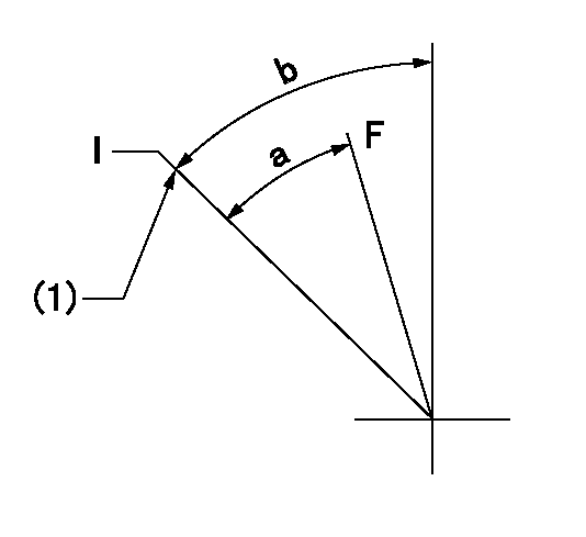
F:Full load
I:Idle
(1)Stopper bolt setting
----------
----------
a=21deg+-3deg b=33deg+-5deg
----------
----------
a=21deg+-3deg b=33deg+-5deg
Stop lever angle
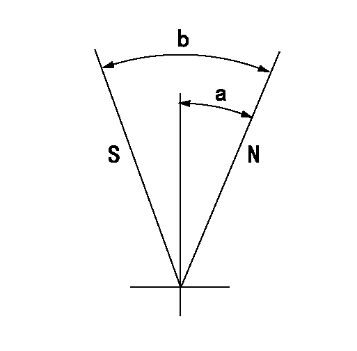
N:Pump normal
S:Stop the pump.
----------
----------
a=35.5deg+-5deg b=71deg+-5deg
----------
----------
a=35.5deg+-5deg b=71deg+-5deg
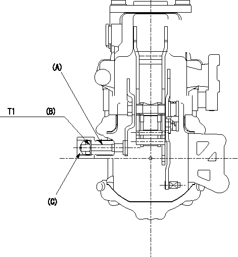
0000001501 TAMPER PROOF
N:Pump speed (r/min)
R:Rack position (mm)
1. After governor adjustment, adjust the shaft as described below and stamp the cap.
(1)Turn the load lever stopper bolt determining the full rack position (R = Ra) 1 - 2 turns counter clockwise.
(2)Then, increase the full rack position.
(3)Operate the pump at N = N1 and turn the shaft (A) clockwise.
(4)Adjust to obtain the full rack +0.4 (R = Rb)
(5)Tighten nut (B) to the specified torque.
(6)Turn the stopper bolt clockwise the same amount that it was turned counter clockwise in (1).
(7)Then, align with the full rack position (R = Ra) and fix.
(8)Apply thread lock adhesive to the entire circumference of the cap (C) and tap it down to pressfit and seal it..
(9)Check for air tightness.
----------
N1=1300r/min Ra=8.7mm Rb=9.1mm
----------
T1=4.9~7N-m(0.5~0.7kgf-m)
----------
N1=1300r/min Ra=8.7mm Rb=9.1mm
----------
T1=4.9~7N-m(0.5~0.7kgf-m)
Timing setting

(1)Pump vertical direction
(2)Position of timer's threaded hole at No 1 cylinder's beginning of injection
(3)B.T.D.C.: aa
(4)-
----------
aa=14deg
----------
a=(60deg)
----------
aa=14deg
----------
a=(60deg)
Information:
The information supplied in this service letter may not be valid after the termination date of this program. Do not perform the work outlined in this Service Letter after the termination date without first contacting your Caterpillar product analyst.
This Program must be administered as soon as possible. When reporting the repair, use "PI3979" as the Part Number, "7751" as the Group Number, "56" as the Warranty Claim Description Code and "T" as the SIMS Description Code. Exception: If the repair is done after failure, use "PI3979" as the Part Number, "7751" as the Group Number, "96" as the Warranty Claim Description Code, and "Z" as the SIMS Description Code.
Refer to your Warranty Bulletin for detailed information in regards to Product Improvement Programs.
Completion Date
June 30, 1997Termination Date
January 31, 1998Problem
During an engine overspeed condition, the engine software may allow the desired injection actuation pressure to exceed the design limits of the unit injector hydraulic pump group, which may result in damage to the pump.
Affected Product
Model & Identification Number
769D (5TR1-216)
771D (6JR1-90)
773D (7ER1-166)
775D (6KR1-99)
Parts Needed
1 - Personality Module (If Needed) Current personality module part numbers can be determided by using NPR, the FIND System, SEHS9914, or the latest SIS Update (Set Up & Tool Guide CD).
Action Required
Replace the software in the engine ECM to March 1996 or newer.
PROCEDURE:
1. Using Caterpillar Electronic Technician (ET) or ECAP service tool, connect to the engine ECM and read the personality module release date.2. If the personality module release date is older than March 1996, replace the personality module or flash the personality module with March 1996 or newer software.Owner Notification
U.S. and Canadian owners will receive the attached Owner Notification.
Service Claim Allowances
Parts Disposition
Handle the parts in accordance with your Warranty Bulletin on warranty parts handling.
MAKE EVERY EFFORT TO COMPLETE THIS PROGRAM AS SOON AS POSSIBLE.
Attach.(1-Owner Notification)Copy Of Owner Notification For U.S. And Canadian Owners