Information injection-pump assembly
ZEXEL
101603-0294
1016030294
ISUZU
1156017765
1156017765

Rating:
Cross reference number
ZEXEL
101603-0294
1016030294
ISUZU
1156017765
1156017765
Zexel num
Bosch num
Firm num
Name
Calibration Data:
Adjustment conditions
Test oil
1404 Test oil ISO4113 or {SAEJ967d}
1404 Test oil ISO4113 or {SAEJ967d}
Test oil temperature
degC
40
40
45
Nozzle and nozzle holder
105780-8140
Bosch type code
EF8511/9A
Nozzle
105780-0000
Bosch type code
DN12SD12T
Nozzle holder
105780-2080
Bosch type code
EF8511/9
Opening pressure
MPa
17.2
Opening pressure
kgf/cm2
175
Injection pipe
Outer diameter - inner diameter - length (mm) mm 6-2-600
Outer diameter - inner diameter - length (mm) mm 6-2-600
Overflow valve opening pressure
kPa
157
123
191
Overflow valve opening pressure
kgf/cm2
1.6
1.25
1.95
Tester oil delivery pressure
kPa
157
157
157
Tester oil delivery pressure
kgf/cm2
1.6
1.6
1.6
Direction of rotation (viewed from drive side)
Right R
Right R
Injection timing adjustment
Direction of rotation (viewed from drive side)
Right R
Right R
Injection order
1-5-3-6-
2-4
Pre-stroke
mm
3.6
3.55
3.65
Beginning of injection position
Drive side NO.1
Drive side NO.1
Difference between angles 1
Cal 1-5 deg. 60 59.5 60.5
Cal 1-5 deg. 60 59.5 60.5
Difference between angles 2
Cal 1-3 deg. 120 119.5 120.5
Cal 1-3 deg. 120 119.5 120.5
Difference between angles 3
Cal 1-6 deg. 180 179.5 180.5
Cal 1-6 deg. 180 179.5 180.5
Difference between angles 4
Cyl.1-2 deg. 240 239.5 240.5
Cyl.1-2 deg. 240 239.5 240.5
Difference between angles 5
Cal 1-4 deg. 300 299.5 300.5
Cal 1-4 deg. 300 299.5 300.5
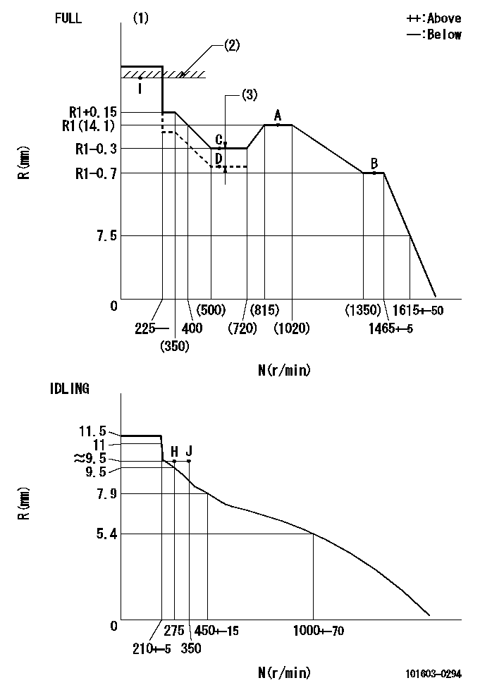
Injection quantity adjustment
Adjusting point
-
Rack position
14.1
Pump speed
r/min
850
850
850
Average injection quantity
mm3/st.
101.2
99.6
102.8
Max. variation between cylinders
%
0
-2.5
2.5
Basic
*
Fixing the rack
*
Standard for adjustment of the maximum variation between cylinders
*
Injection quantity adjustment_02
Adjusting point
-
Rack position
9.7+-0.5
Pump speed
r/min
275
275
275
Average injection quantity
mm3/st.
9.4
8.1
10.7
Max. variation between cylinders
%
0
-14
14
Fixing the rack
*
Standard for adjustment of the maximum variation between cylinders
*
Remarks
Adjust only variation between cylinders; adjust governor according to governor specifications.
Adjust only variation between cylinders; adjust governor according to governor specifications.
Injection quantity adjustment_03
Adjusting point
A
Rack position
R1(14.1)
Pump speed
r/min
850
850
850
Average injection quantity
mm3/st.
101.2
100.2
102.2
Basic
*
Fixing the lever
*
Boost pressure
kPa
20
20
Boost pressure
mmHg
150
150
Injection quantity adjustment_04
Adjusting point
B
Rack position
R1-0.7
Pump speed
r/min
1400
1400
1400
Average injection quantity
mm3/st.
91.9
88.7
95.1
Fixing the lever
*
Boost pressure
kPa
20
20
Boost pressure
mmHg
150
150
Injection quantity adjustment_05
Adjusting point
C
Rack position
R1-0.3
Pump speed
r/min
550
550
550
Average injection quantity
mm3/st.
90.1
86.9
93.3
Fixing the lever
*
Boost pressure
kPa
20
20
Boost pressure
mmHg
150
150
Injection quantity adjustment_06
Adjusting point
D
Rack position
R1-1.75
Pump speed
r/min
550
550
550
Average injection quantity
mm3/st.
52.1
48.9
55.3
Fixing the lever
*
Boost pressure
kPa
0
0
0
Boost pressure
mmHg
0
0
0
Injection quantity adjustment_07
Adjusting point
I
Rack position
-
Pump speed
r/min
150
150
150
Average injection quantity
mm3/st.
92
92
100
Fixing the lever
*
Rack limit
*
Boost compensator adjustment
Pump speed
r/min
550
550
550
Rack position
(R1-0.3)
-1.45
Boost pressure
kPa
2
2
4.7
Boost pressure
mmHg
15
15
35
Boost compensator adjustment_02
Pump speed
r/min
550
550
550
Rack position
(R1-0.3)
-0.95
Boost pressure
kPa
4.7
4.7
7.4
Boost pressure
mmHg
35
35
55
Boost compensator adjustment_03
Pump speed
r/min
550
550
550
Rack position
R1-0.3
Remarks
Measure actual boost pressure.
Measure actual boost pressure.
Test data Ex:
Governor adjustment
N:Pump speed
R:Rack position (mm)
(1)Torque cam stamping: T1
(2)RACK LIMIT
(3)Boost compensator stroke: BCL
----------
T1=B49 BCL=1.45+-0.1mm
----------
----------
T1=B49 BCL=1.45+-0.1mm
----------
Timer adjustment
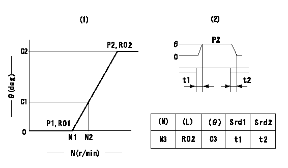
(1)Adjusting range
(2)Step response time
(N): Speed of the pump
(L): Load
(theta) Advance angle
(Srd1) Step response time 1
(Srd2) Step response time 2
1. Adjusting conditions for the variable timer
(1)Adjust the clearance between the pickup and the protrusion to L.
----------
L=1.5+-0.2mm N3=800r/min C3=(6.4deg) t1=2--sec. t2=2--sec.
----------
N1=1200++r/min N2=1500r/min P1=0kPa(0kgf/cm2) P2=392kPa(4kgf/cm2) C1=1.5--deg C2=6.4+-0.3deg R01=0/4load R02=4/4load
----------
L=1.5+-0.2mm N3=800r/min C3=(6.4deg) t1=2--sec. t2=2--sec.
----------
N1=1200++r/min N2=1500r/min P1=0kPa(0kgf/cm2) P2=392kPa(4kgf/cm2) C1=1.5--deg C2=6.4+-0.3deg R01=0/4load R02=4/4load
Speed control lever angle
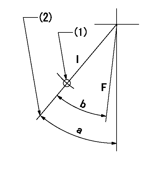
F:Full speed
I:Idle
(1)Use the hole at R = aa
(2)Stopper bolt set position 'H'
----------
aa=35mm
----------
a=43deg+-5deg b=40deg+-3deg
----------
aa=35mm
----------
a=43deg+-5deg b=40deg+-3deg
Stop lever angle

N:Pump normal
S:Stop the pump.
----------
----------
a=25deg+-5deg b=40deg+-5deg
----------
----------
a=25deg+-5deg b=40deg+-5deg
0000001501 RACK SENSOR
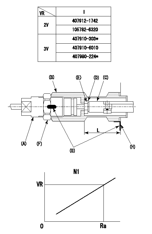
(VR) measurement voltage
(I) Part number of the control unit
(G) Apply red paint.
(H): End surface of the pump
1. Rack limit adjustment
(1)Fix the rack at the rack limit position Ra.
(2)Install the shim (D) to the rod (C) and tighten nut (E).
(3)Select a shim (D) so that the distance between the end surface of the pump and the nut (E) is L.
(4)Release the rack fixing and mount the joint (B) and fix.
(5)At this time, confirm that the shim (D) does not interfere with the joint (B).
2. Rack sensor adjustment (-0420)
(1)Screw in the bobbin (A) until it contacts the joint (B).
(2)Fix the speed control lever at the full side.
(3)Set the speed to N1 r/min.
(4)Adjust the depth that the bobbin (A) is screwed in so that the control unit's rack sensor output voltage is VR+-0.01 (V), then tighten the nut (F).
(5)Adjust the bobbin (A) so that the rack sensor's output voltage is VR.
(6)Apply G at two places.
Connecting part between the joint (B) and the nut (F)
Connecting part between the joint (B) and the end surface of the pump (H)
----------
L=33-0.2mm N1=850r/min Ra=R1(14.1)mm
----------
----------
L=33-0.2mm N1=850r/min Ra=R1(14.1)mm
----------
Timing setting

(1)Pump vertical direction
(2)Position of timer's threaded hole at No 1 cylinder's beginning of injection
(3)B.T.D.C.: aa
(4)-
----------
aa=13deg
----------
a=(60deg)
----------
aa=13deg
----------
a=(60deg)
Information:
The information supplied in this service letter may not be valid after the termination date of this program. Do not perform the work outlined in this Service Letter after the termination date without first contacting your Caterpillar product analyst.
If the work described in this Program was performed on the Affected Product under PI7298, Service Letter dated October 30, 1992, DO NOT repeat the work.
This Revised Service Letter replaces the April 28, 1993 Service Letter revised March 1994. Changes have been made to the TERMINATION DATE and Affected Product.
Termination Date
August 31, 1994Problem
The fuel injection pumps used on certain Remanufactured 1160 and 3208 Engines need to be inspected for gummy deposits.
Affected Product
Model & Identification Number
1160 (57V1-34485)
3208 (9WC1-1093)
3208 (5CD1-9736, 62W1-76455 , 93Z1-10198 )
Parts Stock Remanufactured Fuel Pump Part Numbers
This program applies only to pumps in parts stock with a date code prior to November, 1993 (UUDE). Date codes are in the MM/YY mode with the standard notation of NUMERALKOD.
Parts Needed
Not applicable.
Action Required
Before installing or delivering any of the Affected Product, perform the following steps to ensure the internal fuel injection pump components are not stuck due to fuel pump gumming:
1. Remove the top cover of the fuel injection pump and check to ensure that all sleeves and levers are free and there are no gummy deposits on any of these components.2. If inspection performed in Step 1 indicates everything is clean, install top cover and return to parts stock.3. If inspection reveals components have gummy deposits, remove 12 ounces of fuel from the fuel pump housing and replace it with:- Fuel Injector Cleaneror- Carburetor/Choke Cleaner4. Allow the components to soak in cleaning solution for 45 minutes. Then, rotate the engine crankshaft to rotate the fuel injection pump and check for free movement of the lever and sleeve (on pumps only, rotate the fuel pump camshaft). This will ensure the components have the gummy deposits removed.5. If the above procedures do not free the pump assembly, remove the individual pumps from the pump housing, clean them with cleaning solution, and install them back into the housing.6. If the engine or fuel pump will be used immediately, install the cover on the fuel injection pump, and install or deliver the engine or pump.7. If the engine or fuel pump will be returned to stock, DO NOT leave the fuel injection pump full of cleaning solution because it may not contain any rust inhibitors. Remove the cleaning solution, fill the fuel injector pump with clean diesel fuel, and install the cover on the pump.Service Claim Allowances
The inspection of the pump is a .5-hour job. If the pump needs to be cleaned, an additional .5 hour may be claimed. If the individual pumps need to be removed from the pump housing for cleaning, up to an additional 1.5 hours may be claimed.
US and Canadian Dealers Only - When submitting a Parts Stock claim use 99Z00007 in the Product Identification Number Field.
Parts Disposition
Handle the parts in accordance with your Warranty Bulletin on warranty parts handling.