Information injection-pump assembly
ZEXEL
101603-0051
1016030051
ISUZU
1156014973
1156014973

Rating:
Cross reference number
ZEXEL
101603-0051
1016030051
ISUZU
1156014973
1156014973
Zexel num
Bosch num
Firm num
Name
101603-0051
1156014973 ISUZU
INJECTION-PUMP ASSEMBLY
6BB1 * K
6BB1 * K
Calibration Data:
Adjustment conditions
Test oil
1404 Test oil ISO4113 or {SAEJ967d}
1404 Test oil ISO4113 or {SAEJ967d}
Test oil temperature
degC
40
40
45
Nozzle and nozzle holder
105780-8140
Bosch type code
EF8511/9A
Nozzle
105780-0000
Bosch type code
DN12SD12T
Nozzle holder
105780-2080
Bosch type code
EF8511/9
Opening pressure
MPa
17.2
Opening pressure
kgf/cm2
175
Injection pipe
Outer diameter - inner diameter - length (mm) mm 6-2-600
Outer diameter - inner diameter - length (mm) mm 6-2-600
Overflow valve
132424-0620
Overflow valve opening pressure
kPa
157
123
191
Overflow valve opening pressure
kgf/cm2
1.6
1.25
1.95
Tester oil delivery pressure
kPa
157
157
157
Tester oil delivery pressure
kgf/cm2
1.6
1.6
1.6
Direction of rotation (viewed from drive side)
Right R
Right R
Injection timing adjustment
Direction of rotation (viewed from drive side)
Right R
Right R
Injection order
1-5-3-6-
2-4
Pre-stroke
mm
2.4
2.35
2.45
Beginning of injection position
Drive side NO.1
Drive side NO.1
Difference between angles 1
Cal 1-5 deg. 60 59.5 60.5
Cal 1-5 deg. 60 59.5 60.5
Difference between angles 2
Cal 1-3 deg. 120 119.5 120.5
Cal 1-3 deg. 120 119.5 120.5
Difference between angles 3
Cal 1-6 deg. 180 179.5 180.5
Cal 1-6 deg. 180 179.5 180.5
Difference between angles 4
Cyl.1-2 deg. 240 239.5 240.5
Cyl.1-2 deg. 240 239.5 240.5
Difference between angles 5
Cal 1-4 deg. 300 299.5 300.5
Cal 1-4 deg. 300 299.5 300.5
Injection quantity adjustment
Adjusting point
A
Rack position
9.3
Pump speed
r/min
1000
1000
1000
Average injection quantity
mm3/st.
51.2
49.7
52.7
Max. variation between cylinders
%
0
-2.5
2.5
Basic
*
Fixing the lever
*
Injection quantity adjustment_02
Adjusting point
-
Rack position
7.5+-0.5
Pump speed
r/min
325
325
325
Average injection quantity
mm3/st.
9.4
8.1
10.7
Max. variation between cylinders
%
0
-14
14
Fixing the rack
*
Remarks
Adjust only variation between cylinders; adjust governor according to governor specifications.
Adjust only variation between cylinders; adjust governor according to governor specifications.
Injection quantity adjustment_03
Adjusting point
C
Rack position
-
Pump speed
r/min
100
100
100
Average injection quantity
mm3/st.
51
51
Fixing the lever
*
Remarks
After startup boost setting
After startup boost setting
Timer adjustment
Pump speed
r/min
1050--
Advance angle
deg.
0
0
0
Remarks
Start
Start
Timer adjustment_02
Pump speed
r/min
1000
Advance angle
deg.
0.5
Timer adjustment_03
Pump speed
r/min
1200
Advance angle
deg.
0.9
0.4
1.4
Timer adjustment_04
Pump speed
r/min
1450
Advance angle
deg.
2.1
1.6
2.6
Timer adjustment_05
Pump speed
r/min
1650
Advance angle
deg.
3
2.5
3.5
Timer adjustment_06
Pump speed
r/min
-
Advance angle
deg.
5
5
5
Remarks
Measure the actual speed, stop
Measure the actual speed, stop
Test data Ex:
Governor adjustment
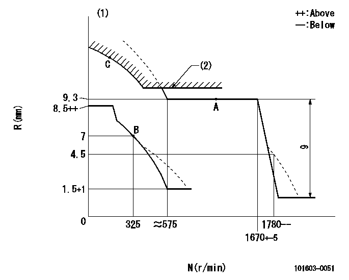
N:Pump speed
R:Rack position (mm)
(1)Damper spring setting: DL
(2)Excess fuel setting for starting: SXL
----------
DL=5.2-0.2mm SXL=9.5+0.2mm
----------
----------
DL=5.2-0.2mm SXL=9.5+0.2mm
----------
0000000901
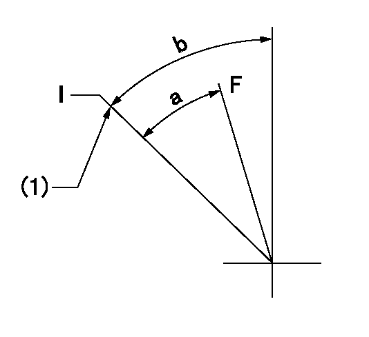
F:Full load
I:Idle
(1)Stopper bolt setting
----------
----------
a=27deg+-3deg b=33deg+-5deg
----------
----------
a=27deg+-3deg b=33deg+-5deg
Stop lever angle
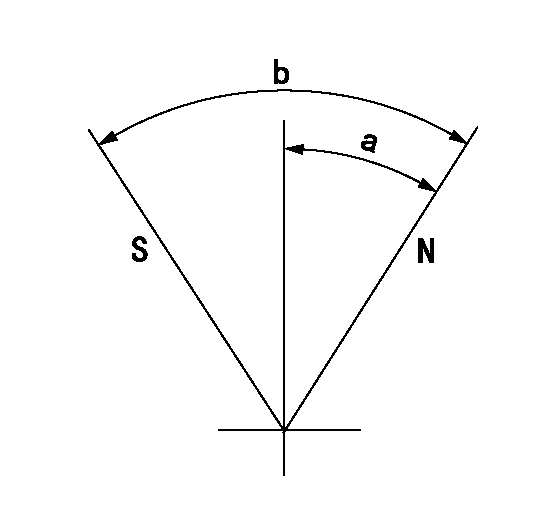
N:Pump normal
S:Stop the pump.
----------
----------
a=35.5deg+-5deg b=71deg+-5deg
----------
----------
a=35.5deg+-5deg b=71deg+-5deg
Timing setting

(1)Pump vertical direction
(2)Position of timer's threaded hole at No 1 cylinder's beginning of injection
(3)B.T.D.C.: aa
(4)-
----------
aa=14deg
----------
a=(60deg)
----------
aa=14deg
----------
a=(60deg)
Information:
start by: a) remove fuel injection pump housing and governor 1. Install the fuel injection pump housing on tool (A). 2. Remove the bolt (1) from the cover. Turn the injection pump camshaft until the timing pin (B) can be installed in the camshaft.3. Install tool (C) in the threads of the sleeve (3). Tighten the bolt until the sleeve can be removed.4. Remove the four bolts (4) that hold the body to the housing.5. Remove the body (2) from the housing. 6. Remove the idler gear (5) from the body.7. Remove the O-ring seal (6) from the body. Remove the two lip type seals (7) from the body. 8. Remove the drive gear (9) from the shaft.9. Remove the key (8) from the shaft.Install Fuel Transfer Pump
1. Install the key (1) and the drive gear (2) on the shaft.2. Put 5S1454 Sealing Compound on the outside diameter of the seals. 3. Install the inner seal in the body with the lip of the seal toward the inside with tooling (A).4. Install the outer seal in the body with the lip of the seal toward the outside with tooling (B).5. Remove the extra sealing compound from the body and the seals after installation. 6. Install the O-ring seal (4) and the idler gear (3) in the body. 7. Install the body (5) on the housing. 8. Install the four bolts (7) that hold the body to the housing.9. Put the timing pin (D) in position to keep the camshaft from turning.10. Put the sleeve (6) on the camshaft. 11. Tighten the sleeve into position on the shaft with 4B4280 Washer of tooling (C) approximately .25 in. (6.4 mm). Tighten the sleeve the remainder of the way with the 4N3371 Washer. The 4N3371 Washer is the washer which is on the tachometer drive bolt.
Do not hit the sleeve to install. Damage to governor will result.
12. The end play of the camshaft must be .023 .018 in. (0.58 0.46 mm) after sleeve (6) is installed.end by: a) install fuel injection pump housing and governor
Have questions with 101603-0051?
Group cross 101603-0051 ZEXEL
Isuzu
101603-0051
1156014973
INJECTION-PUMP ASSEMBLY
6BB1
6BB1